
A packaging machine stops when its guard opens. The operator reaches between the sealing jaws to pull out a strip of film. At commissioning, someone tested that stop. Six months later, a service engineer replaces the safety controller and restores a program from a memory card. What makes the commissioning result true today?
That is where machinery cybersecurity begins for a machine builder. The EU Machinery Regulation calls this protection against corruption. A change can be deliberate, or an engineer can pick the wrong file on a perfectly ordinary Tuesday. In either case the question at the machine is the same. Can the jaws move while someone has a hand between them?
The English enquiry draft prEN 50742:2025 gives the designer a way to answer. It starts with the machine risk assessment, identifies the connections through which protection could be compromised and leads to a decision the commissioning engineer can test. Three jobs will carry that through: clearing film from a packer, adjusting a guide beside a moving carriage and unloading a hot part from a cooling station.
Start with the protection the operator relies on
Open the ISO 12100 risk assessment at the task in question. Who is exposed? Where is the source of harm? What prevents it from reaching the person? On the packer, the task is clearing a jam, the source is the closing movement of the jaws and the possible injury is crushed fingers. Opening the guard has to stop hazardous movement and prevent an unexpected start while the guard remains open. Machine risk assessment at the human–machine interface.
Now ask the service engineer how a replacement controller gets its program. The electrical drawing shows a USB port. The engineer knows which laptop connects to it, where the backup lives and whether anyone checks the active version after a restart. Those details tell the designer how the protection could change over the machine’s life.
In a risk register, a cyber threat can be recorded against that task. Replacing the safety program is the intervention. The moving jaws are still the physical hazard. ISO 12100 calls for identification of hazardous situations and/or hazardous events. A separate event entry is useful when it explains the route to harm. Foreseeable hazards that cannot be tied to one particular task also belong in the assessment.
Which route through prEN 50742 fits the project?
Approach A gives the machine builder a process for the threat assessment and machinery-specific product requirements. Approach B uses the secure product development requirements of EN IEC 62443-4-1, with specified requirements from EN IEC 62443-3-3 for systems and EN IEC 62443-4-2 for components. The draft identifies the applicable requirements and capability levels (SL-C) in its system and component tables. Both routes start with the ISO 12100 assessment, address protection against corruption and produce information for use.
An Ethernet socket makes a useful starting point for tracing a connection. Its shape tells you very little about the decision. One socket leads to a local display. Another gives a remote service tool write access to the speed limit. Follow the connection as far as the value or behaviour it can change.
Four entries turn a service connection into an engineering decision
- 1.A · Security context. Draw the limits of the analysis. Record who can reach the machine, from where, for how long and with what privileges. Include temporary connections and the access controls the site is expected to supply.
- 1.B · List of threats. Name the change and its route. For example, a replacement safety program can reach the packer through the socket on the cabinet door.
- 1.C · Impact analysis. Establish what it would take to exploit the vulnerability, which protection would be lost and who might be hurt. An independent measure may still prevent access. Check that it really is independent of the changed data.
- 1.D · List of threats requiring attention. Decide whether the existing protection is adequate. If a person can reach moving jaws after a program change, identify the change the design must prevent or detect. If the threat is already adequately mitigated, record the reason.
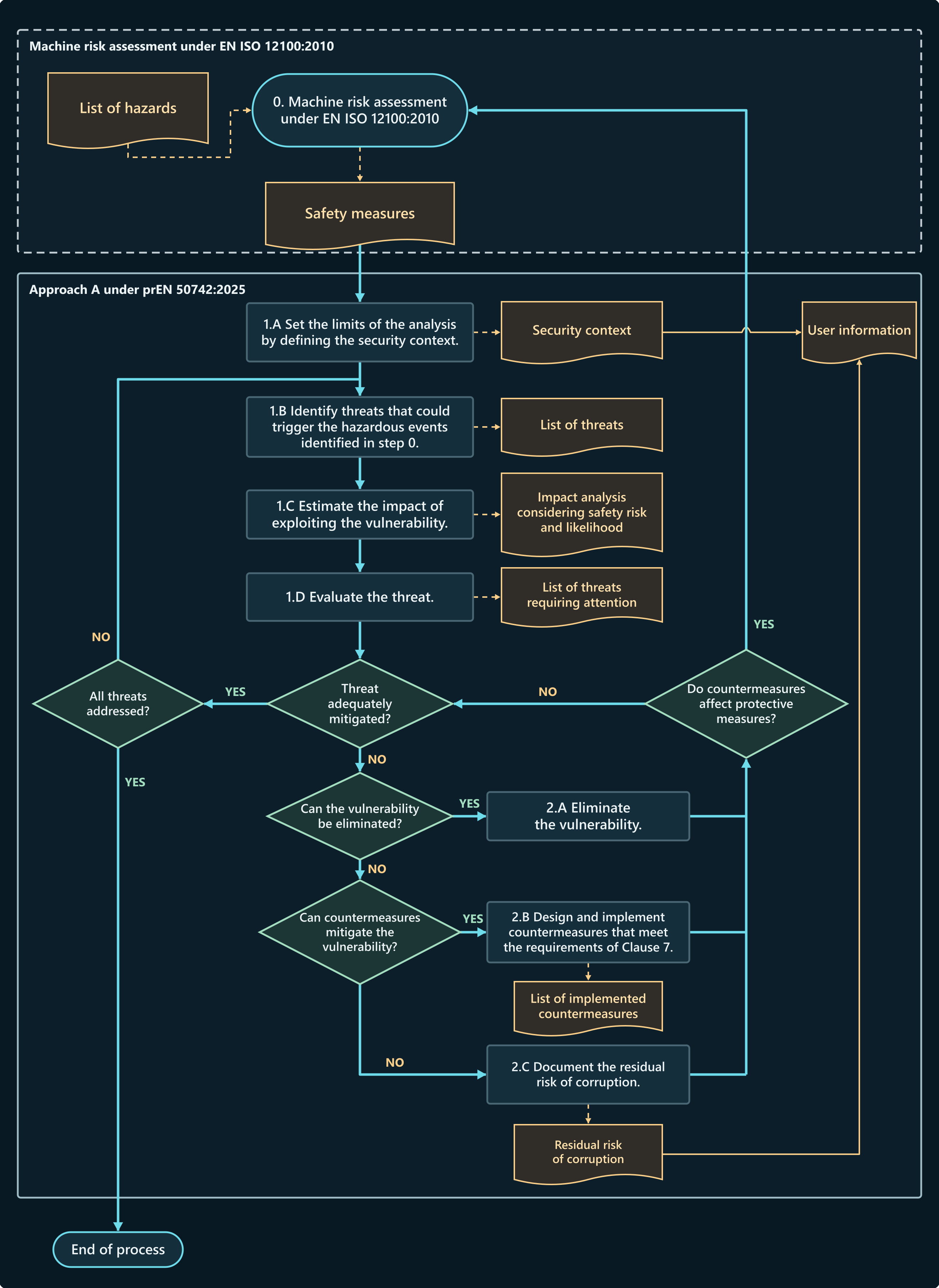

Figure 1 of the enquiry draft calls the output of step 0 safety measures. ISO 12100:2010 uses protective measure. The later ISO/DIS 12100.3 draft uses risk reduction measure as its preferred term. For the packer, the practical question survives all three wordings: which measure keeps the jaws from closing, and what can interfere with it?
How to determine a safety-related security level
Under Approach A, the manufacturer determines and documents a safety-related security level (SRSL) for each identified safety function. This sets the minimum protection required against corruption. Annex B offers a scoring method. The choice of level needs justification even when a manufacturer uses a different method.
In the Annex B method, work through one function and one interface or connection at a time. Estimate the attack potential (AP) and use the machine risk assessment to establish the severity of harm if the intervention succeeds. Guessing how likely a criminal is to take an interest in this particular factory adds nothing to that calculation.
AP = (EL × WoO) + AC
Choose three inputs
- Exposure level (EL). Where can the interface be reached from? The scores are 0 for an internal connection in the trusted environment (EL0), 2 for physical access at its boundary (EL1), 5 for local operational technology network access (EL2), 16 for the wider site network (EL3) and 24 for an external, untrusted network (EL4). Use the higher exposure where the connection spans two levels.
- Window of opportunity (WoO). Consider the machine as a whole in its actual security context. Very restricted access, such as access under constant supervision, gives a multiplier of 0.6. Occasional predictable access under moderate control gives 0.8. Regular opportunities with little control give 0.9. Open or unrestricted access gives 1.
- Attacker capability (AC). How much knowledge and skill would the intervention take? Deep system knowledge and advanced skills score 1. Moderate knowledge with specialist skills scores 2, or 3 with intermediate skills. Basic knowledge and simple tools score 4. The easier the change, the higher the score.
Calculate the score, then look at the injury
The draft illustrates a bus between a safety controller and the ordinary machine controls. The link spans EL1 and EL2, so take 5 points. Access is moderately restricted (0.8), and basic skills suffice (4). The arithmetic is (5 × 0.8) + 4 = 8. That puts the connection in AP1. Both severity columns below give SRSL1.
Annex B selection by attack potential and severity of harm
| AP score | Class | Low severity, e.g. reversible injury | High severity, e.g. irreversible injury |
|---|---|---|---|
| 0–5 | AP0 | SRSL0 | SRSL0 |
| 5.1–10 | AP1 | SRSL1 | SRSL1 |
| 10.1–15 | AP2 | SRSL1 | SRSL2 |
| 15.1–20 | AP3 | SRSL2 | SRSL3 |
| Above 20 | AP4 | SRSL3 | SRSL3 |
Read the first row alongside the main text. The draft reserves SRSL0 for a completely isolated safety system. If a technician can plug in and overwrite the safety program, the designer still has a route to account for, however small the numerical score looks. Technical sources and table references.
A carriage makes the difference between SRSL2 and SRSL3 tangible
A setter opens a guard to adjust a guide. A drive monitors carriage speed throughout the adjustment. In this design, someone on the wider factory network can raise the limit. The site opens the connection for monthly servicing under moderate access control. Changing the value takes only basic skills.
Here (16 × 0.8) + 4 = 16.8 → AP3. The setter’s hand could suffer permanent injury, so the table gives SRSL3. With the same connection and a justified low-severity consequence, that row would give SRSL2. Severity belongs to the person and the task. The drive model alone cannot supply it.
That decision changes the acceptance test. On a controlled test rig, the engineer alters a message on its way to the drive, then replays a previously valid message. At SRSL3 the secure cryptographic protocol has to detect and reject both. A separate test uses the diagnostics account to request a higher limit. Reading the value should work. Writing it should fail. Read the active limit back.
What changes as the level goes up?
The required performance level (PLr) for the speed-monitoring function expresses the risk reduction required of the safety-related control system. Its achieved PL addresses how reliably the function performs. SRSL brings a different design question to the same drive. Who can alter the limit, and how will the drive recognise corrupted data?
| Design decision | Selected requirements in Approach A |
|---|---|
| Who can intervene? | SRSL1 and SRSL2 require authentication of the person, process or device and authorisation for an intervention. SRSL3 requires unique authentication and specific privileges for the action. |
| When is integrity checked? | Check safety-related software and critical settings at start-up for SRSL1. SRSL2 adds periodic checks during operation. SRSL3 requires cryptographic verification at both times. |
| What reaches the receiver? | SRSL1 and SRSL2 require verification of the integrity of exchanged information. At SRSL3 a secure cryptographic protocol detects and rejects modified or replayed messages. |
| Which file can be installed? | SRSL2 and SRSL3 require the authenticity of critical data to be verified at installation, for example by a digital signature. The corresponding SRSL1 entry sets no installation-time authenticity requirement. |
Choose a countermeasure and decide when the work is finished
Step 2.A asks whether the design can eliminate the vulnerability. A programming socket fitted for development can sometimes go altogether. If service still needs to write to the controller, move to 2.B. Design and implement the countermeasures for the access that remains and record them. At 2.C, document the residual risk of corruption and what the user must do about it.
These decisions can apply to different routes on the same machine. Removing a socket from the door eliminates one route. The socket inside the cabinet still needs protection. A warning in the manual cannot make an exposed operator safe while a technically inadequate design stays in service.
What does a seal actually do? At SRSL1, SRSL2 and SRSL3 the draft requires physical tampering to be detected. A tamper-evident seal across a memory-card cover can show that the cover was opened. The technician then knows where to investigate. Checking the active program establishes whether anything was changed. A network write can leave that seal in mint condition.
A seal can also provide physical evidence of intervention where collecting digital evidence is not reasonably practicable. Explain where the evidence is, how to inspect it and what to do if it is missing or damaged. A record of authorised program changes matters too. Opening a guard a thousand times is ordinary operation. Changing the program that decides what happens on the next opening is an intervention.
What should be in the record?
The machine must automatically collect the required intervention evidence. A digital record identifies the type of intervention and allows it to be correlated with other events, for example by a timestamp or a boot counter. Deleting the log file is itself recorded. Protect the records against tampering and restrict any permitted deletion to an authorised procedure. Service staff must be able to identify safety-relevant software versions and configuration on demand.
Two five-year rules have different starting points. Under the Machinery Regulation, when safety software is uploaded after placing on the market or putting into service, the relevant tracing log of intervention and versions must be enabled for five years after that upload. In Approach A, the draft calls for at least five years’ retention of each intervention record, with logging enabled at least from putting into service.
Before the test, write down the attempted change, expected response and conditions for restarting. Record the access route, privileges, active configuration and actual response. If a new countermeasure slows the safety function, take the timing back to the machine risk assessment. A stop command in the log is scant consolation if the carriage was still moving when the setter could reach it.
The manufacturer can close the assessment when the threats have been addressed and the evidence supports adequate risk reduction in the defined security context. Give the user the operating conditions and remaining precautions that conclusion depends on. A new remote connection or a different backup process changes those assumptions and reopens the affected decisions.
Three entries for the machine’s technical documentation
The packer draws on the vertical form, fill and seal machine in Annex C of the draft. The following service arrangements, acceptance criteria, carriage and cooling station are worked engineering examples. The values are design assumptions for those examples.
Packaging machine: clearing a jam after a controller replacement
The operator opens the interlocking guard and reaches for trapped film. The safety controller must stop the sealing, perforating and cutting mechanisms and prevent unexpected start-up while the guard is open. The threat assessment starts at the two places a different program could get in.
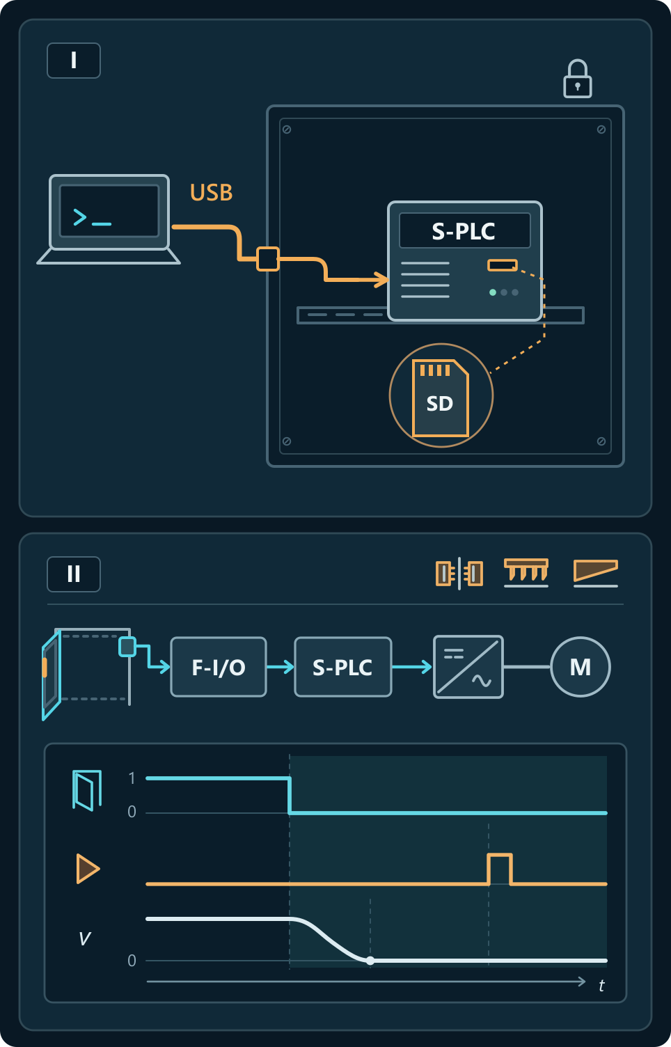
- 1.A · Context. The safety PLC and memory card are in a locked cabinet. During a stop, the external USB socket accepts a programming laptop without individual sign-in.
- 1.B · Threat. Someone loads a program through that socket which permits the jaws to close with the guard open.
- 1.C · Impact. A stopped machine, the programming tool and physical access to the port are sufficient in this design. The next person clearing film could have their fingers crushed.
- 1.D · Decision. Control program writes. Acceptance evidence must include the active version after an unauthorised write attempt and the physical guard-interlock test.
- 2.A · Eliminate. Service can work inside the cabinet. Remove the external socket and its cable.
- 2.B · Mitigate. At the remaining internal connection, permit program downloads only to a service user with write privileges. Keep diagnostic access read-only.
- 2.C · Residual risk. An unattended laptop with an authorised session could still be used to change the interlock. Require the engineer to end the session before walking away. After suspected interference, keep the machine out of service until the program and guard function have been checked.
If safety-related application software is changed remotely, EN ISO 13849-1 also addresses validation of the affected safety functions on site. The ability to connect again from the office settles very little about what the jaws actually do.
Carriage: a genuine backup for the wrong station
At station A the setter watches the carriage from behind a guard. At B the guide must be adjusted with the guard open, so B has a lower permitted speed. Specify the access conditions, speed limit and maximum stopping time in the safety requirements specification (SRS). Writing an SRS under ISO 13849-1.
The AP3 calculation considered a network write. A replacement drive introduces a second way to change the same limit, this time with a fully authorised service engineer.
- 1.A · Context. A and B use the same model of drive. Their backups are in one folder and the service engineer has permission to restore either file.
- 1.B · Threat. The engineer restores A’s genuine backup to B. The file carries the higher limit.
- 1.C · Impact. Raising the limit does not command acceleration. The danger appears when actual speed passes B’s limit but stays below A’s. The carriage can continue towards the setter when it should already be stopping.
- 1.D · Decision. B must reject A’s file and inhibit motion that depends on speed monitoring until it accepts the correct settings. The inhibit must survive a restart.
- 2.A · Eliminate? The engineer needs to restore settings after drive replacement, so this write path stays.
- 2.B · Mitigate. Verify the package signature and compare its station identifier with B’s protected identifier, stored outside the replaceable drive. A signed package for A must still fail at B.
- 2.C · Residual risk. A person authorised to release B’s package could approve the wrong numerical limit for B. Check the commissioned value and test overspeed against the SRS before releasing the station.
Two healthy channels can agree on exactly the wrong speed when both read the same parameter. How ISO 13849-1 categories handle faults.
Acceptance tests for station B
| Attempt | Expected machine response | Evidence to retain |
|---|---|---|
| Raise the limit from the read-only account. | Reading succeeds. The drive rejects the write and retains the approved limit. | Connection, privileges, drive response and active value before and after the attempt. |
| Restore A’s backup to B after drive replacement, then restart B. | B rejects the file. Monitored motion remains inhibited after restart and until B’s settings are accepted. | Station and file identifiers, rejection reason and state of the inhibit after restart. |
| With B’s correct file installed, exceed its limit in a controlled test. | The monitor initiates a stop and the carriage comes to rest within the time specified in the SRS. | Configuration version, mode, load, measured speed and stopping time against the acceptance criteria. |
Define the test load and stopping criteria first. Read back the active parameter after power-up. If the main controller downloads the limits at boot, include its backup in the assessment. Otherwise a successful drive test can last precisely until the next power cycle.
Cooling station: the timer is right and the part is still hot
The operator unloads a heat-treated part by hand. The risk assessment permits access once its surface has cooled sufficiently. In the original design the recipe timer releases the guard lock. Change twelve minutes to six and the timer will deliver six minutes with admirable precision. It has no temperature input.
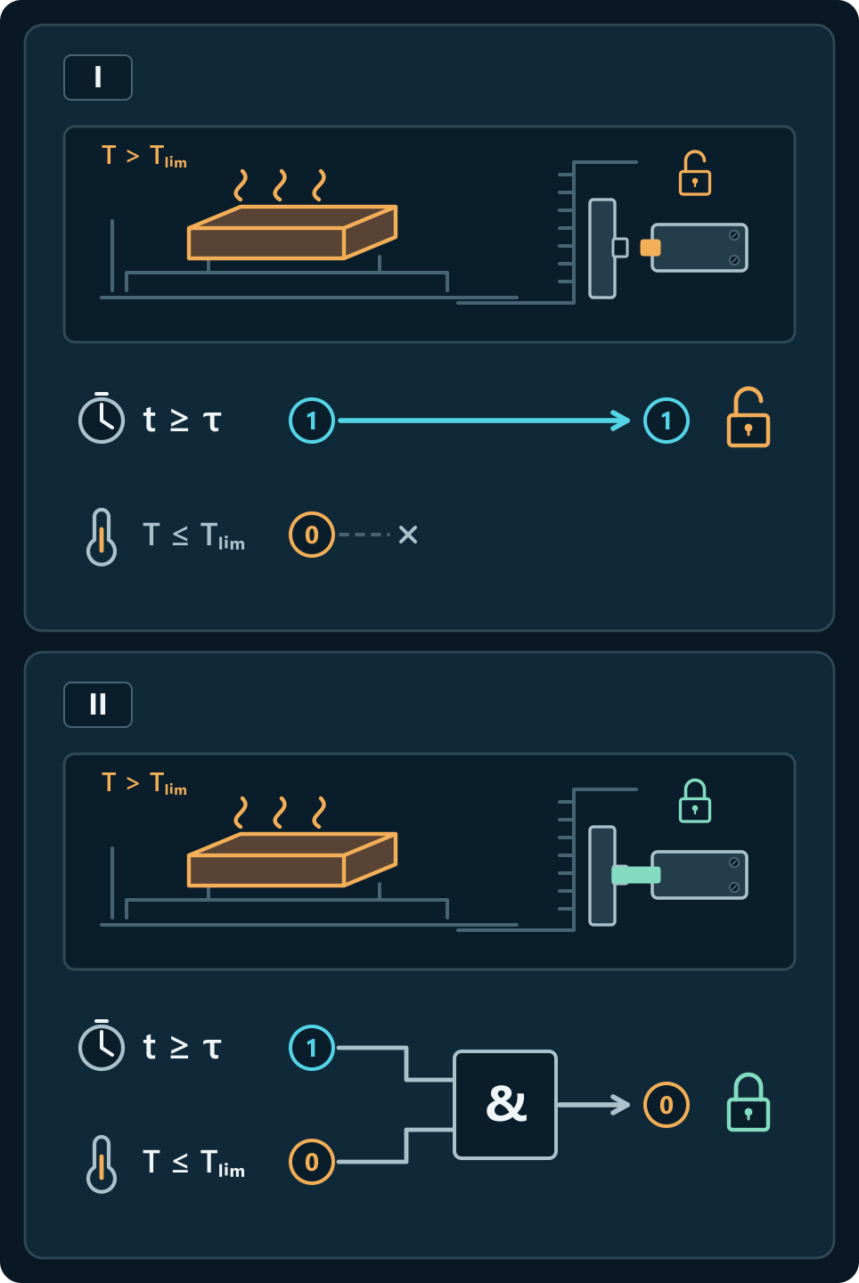
- 1.A · Context. The process engineer can edit cooling time from the production account. The original machine has no part-temperature measurement.
- 1.B · Threat. A recipe change from twelve to six minutes also advances guard unlocking by six minutes.
- 1.C · Impact. Normal production privileges are enough. A heavier part can still burn the operator’s hand on unloading.
- 1.D · Decision. Changing cycle time must leave the door locked whenever the surface the operator will touch exceeds the validated limit.
- 2.A · Eliminate. Remove the recipe’s authority to unlock the door on its own. Require independent confirmation that the part has cooled.
- 2.B · Mitigate. Let production set cycle time. Restrict changes to the temperature threshold and sensor correction to authorised service personnel. Loss of the measurement must keep the guard locked.
- 2.C · Residual risk. An incorrect correction after sensor replacement can make a hot part appear cool. Before restoring manual unloading, compare the reading with an independent measurement on the part near the unlocking threshold.
A time-based design is also an engineering option if the manufacturer establishes and protects a safe minimum for the permitted parts, starting temperatures and cooling conditions. In either design the acceptance criterion belongs to the surface the person touches.
What the Machinery Regulation requires
Regulation (EU) 2023/1230 generally applies from 20 January 2027. Its essential health and safety requirements cover safety-critical software and data, relevant hardware through which they can be accessed, and control systems exposed to reasonably foreseeable malicious attempts. They also address evidence of interventions and identification of the software relevant to safe operation. How the Machinery Regulation treats software, data and cyber risk.
Annex ZZ of the 2025 enquiry draft maps its provisions to Annex III, point 1.1.9 (Protection against corruption), and specified parts of point 1.2.1 on control systems. A manufacturer can use a draft as a technical specification and document the measures and tests chosen. Under Article 20, a presumption of conformity depends on compliance with the relevant provisions of a harmonised standard whose reference has been published in the Official Journal of the European Union. Check the cited edition, coverage, restrictions and applicable conformity assessment procedure before drawing up the declaration.
Where the Cyber Resilience Act adds work
Suppose someone copies the cooling recipe without changing the cycle. The operator still handles the part under the same conditions, but the customer’s process data have left the plant. Where the machine is also a product with digital elements in scope of the Cyber Resilience Act (CRA), the cybersecurity assessment extends to risks such as loss of confidentiality. Evidence from the guard-lock test can support both assessments for the risks it actually addresses.
The CRA brings product-design duties and vulnerability handling throughout the support period. This includes providing necessary security updates. Its reporting obligations for actively exploited vulnerabilities and severe incidents affecting product security apply from 11 September 2026. Most provisions apply from 11 December 2027.
The Commission’s guidance of 27 July 2026 also explains the transitional treatment of qualifying EU-type examination certificates and approval decisions under the Machinery Regulation. For cyber risks already assessed and covered, a manufacturer may rely on such a document while it is valid and at the latest until 11 June 2028. Additional risks within the scope of the CRA still require assessment. The documents and the tests matter because each one answers a particular question about a particular product.
Technical sources
- prEN 50742:2025, Safety of machinery — Protection against corruption. English CENELEC enquiry text, OVE draft issue of 15 January 2026. Clauses 4–6, Table 1 and Figure 1 for scope and workflow. Clause 7.4.2 and Table 2 for determining SRSL. Informative Annex B, Tables B.1–B.6 for exposure, capability, opportunity, AP bands and severity mapping. Clause 7.4.3 for level-specific measures, Clauses 7.3 and 7.5 for evidence and identification, Clause 8 and Tables 3–4 for Approach B, Clause 9 for information for use. Annex C.3.2, C.4.2 and C.5.2 for the packaging example. Annex ZZ, Table ZZ.1 for the intended regulatory coverage.
- Machine risk assessment and terminology. ISO 12100:2010, Clauses 3, 5 and 6, especially 5.4 and informative Annex B. Compare Clause 3.19 with Clause 3.17 of ISO/DIS 12100.3. The technical report ISO/TR 22100-4:2018 discusses the interface between IT security and machine safety in Clauses 4.3, 6, 9 and 10 and Figure 3. ISO 12100 · ISO 12100 revision project · ISO/TR 22100-4.
- Control systems and industrial security. ISO 13849-1:2023, Clauses 5.2.4 and 7.4 on remote access, configuration and safety-related application software. Approach B references EN IEC 62443-4-1:2018, EN IEC 62443-3-3:2019 and EN IEC 62443-4-2:2019. ISO 13849-1 · Secure product development · System requirements · Component requirements.
- Machinery Regulation. Article 20(1), Article 25, Annex III points 1.1.9 and 1.2.1 (including second paragraph, points (a) and (f)), and Annex IV Part A, points (f)–(g). Regulation (EU) 2023/1230, consolidated text · Corrigendum on the dates of application.
- Cyber Resilience Act. Recital 53, Articles 2, 13, 14, 69 and 71 and Annex I. European Commission guidance C(2026) 5252, annex, paragraphs 255–257 on the machinery interface. Regulation (EU) 2024/2847 · European Commission guidance.