

An operator opens the guard of a machining centre, slides a workpiece into the clamp and holds it by hand to position it before clamping. He tries to start the clamp. The machine refuses: the open guard blocks the movement.
That is exactly how it was designed. Production still has to start somehow.
Imagine we are watching this during acceptance testing. The cabinet contains proven components, and a performance level calculation report lies on the table. The designer has the circuit diagram, sensor data and the manufacturer’s library. The operator has a workpiece in his hand. His task was not agreed with the same precision.
The control system performs its assigned function correctly. The missing question came earlier: how is the person supposed to clamp the part? A safety requirements specification, or SRS, should close that gap before an unstated assumption is ordered, installed and programmed.
ISO 13849-1:2023 requires the results of the risk assessment performed according to ISO 12100. From those results, we derive the safety functions, required behaviour and required performance level, or PLr. We record them in the SRS, which forms part of the technical documentation and provides the basis for the subsequent design.
Component selection, calculations, verification and validation come later. Before starting that work, establish where the operator’s hand will be during clamping. That answer will not be in the controller catalogue. The distinction between PL and SIL, and why machinery projects so often use PL, is discussed further in ISO 13849-1.
How do you clamp the workpiece safely when the system is already built?
Go back a few weeks. The project is accelerating because someone proposes a proven package from the previous machine: a guard sensor, controller and suitable drive. The data are available, the library is ready and the supplier knows the deadline.
The question of manually positioning the workpiece is postponed until commissioning. By then, everyone will be able to see what happens.
And now they can. The operator needs movement while the guard is open, but the control system is designed to stop that movement. Someone proposes adding an exception to the programme. The purchased devices have started to dictate the protective requirements, although they should have been selected to implement them.
Pause the discussion at the clamp. Why must the operator support the workpiece? Could the tooling locate it before clamping? Which movement is genuinely necessary, and which would disappear if the clamping method changed?
The protective concept depends on those answers. The clamp may need to change. Movement during access may still be necessary, in which case its permitted conditions, limits and stopping behaviour must be specified. An exception in the logic does not, by itself, make the task safe.
The same controller, a different task
Loading may have worked differently on the previous machine. Perhaps its tooling supported the deposited workpiece, allowing the operator to close the door before clamping. Here, the operator’s hand remains inside for longer.
The controller part number matches. The conditions of use may not. Before reusing the old design, check access, task sequence, required movements and load behaviour. “It worked on the previous machine” still describes the previous machine.
These findings can change drawings, device selection and software. They are much harder to accept once the cabinet is complete and the schedule contains only one remaining box marked “acceptance”. At that point, the operator’s hand is also preventing the project from closing.
Repeating the circuit calculation will not settle the dispute at the clamp. The achieved PL applies to the implemented function under the conditions used for its assessment. If the assessed function was stopping movement when the guard opens, the result will not create missing requirements for manual clamping.
You can have two channels and not one requirement for the task the operator is actually performing.
Certified devices and previously validated subsystems are useful, and ISO 13849-1 permits their use when the integration conditions are met. But the complete safety function must still be demonstrated in the actual application, with its clamp, load and access conditions. The controller manufacturer does not know how your workpiece is positioned. Its certificate never assessed that task.
For the control engineer, this is a crucial boundary of responsibility. The devices may be wired correctly, the logic may be sound and the PL may be justified, yet the assignment can still be incomplete. The engineer needs the risk assessment results before assumptions become embedded in software.
If those results are missing, return to the design team. Decide how this specific task is to be protected: who decides on the clamp, who identifies the necessary movements, and who defines the access conditions. Programming should begin from an agreed requirement.
Put the catalogue aside and walk through the entire task with the operator, especially the beginning that takes place before the guard closes. Only then can the team define what is required from the safety-related parts of the control system, or SRP/CS.
The operator enters the design before the guard closes
The operator brings the workpiece, places it, adjusts its position and clamps it. Only then does the guard close and machining begin. At the end, the operator opens the door again and removes the part.
If the task description began at the START button, it omitted the very operation without which there is no reason to press that button.
Add an incorrectly presented workpiece, tool replacement, cleaning and restart after an interruption. During each intervention, the person may stand somewhere different, closer to other movements and energy sources.
“Operate according to the instructions” does not show the designer how the work is actually performed. Nor does it establish which movements may occur or which parts must remain stationary.
ISO 12100 starts with the determination of the limits of the machinery and its use. Identify users, modes, materials and interventions. Consider the machine’s life-cycle phases and reasonably foreseeable misuse.
Only then identify hazards and estimate risk. Risk evaluation follows: decide whether risk reduction is required. This turns “clear a jam” from one convenient line into a real task involving access from a particular side and controlled movement of the mechanism.
A conversation at the machine exposes this quickly. If the protective arrangement prevents a necessary task, it may also encourage defeat of the safeguards. Correct the design before bypassing becomes the workshop’s normal operating method.
Perhaps the best answer is to change the clamp
The first decision about this clamping problem may have nothing to do with the controller. Tooling that locates the workpiece without a hand in the clamping area changes the operator’s exposure at source.
ISO 12100 begins risk reduction with inherently safe design measures. Protective measures such as guards or protective devices come next, together with complementary protective measures. Information for use follows after that.
Once the protective concept is selected, define the control tasks. The control system may have to prevent specified movements during access, permit necessary setting movements and maintain the workpiece after pressure is lost. Those decisions lead to the safety functions and their scope.
Operator tasks reveal an important part of the problem, but the assessment covers the whole machine. Ejected material, noise and structural failure still matter even when no manual intervention is taking place.
The complete decision process is illustrated in this ISO 12100 risk assessment example. When selecting protection, it is also useful to examine the role of technical protective measures.
ISO 13849-1 expects the safety requirements specification
Clause 4.5 of ISO 13849-1:2023 requires the results of the risk assessment, information about the necessary safety functions, their contribution to risk reduction and their PLr. Clause 5.1 refers directly to detailed information from the assessment according to ISO 12100.
These are design inputs. Starting with the electrical drawing does not produce them, although it does make the first page of the documentation appear more quickly.
The SRS describes the functions and functional requirements, assigns PLr and is reviewed for completeness before design. That is the sequence established by Clauses 5.1 to 5.4. The PLr belongs in the completed SRS.
An earlier record without PLr remains a working draft. “To be determined during commissioning” gives the team a deadline for more work; it does not close a safety requirement.
The mechanical designer knows the clamp, the process engineer knows how the part is positioned, the user knows the interventions, and the control engineer knows the control capabilities. The SRS records the result of their joint decision. This is the right moment to discover that a planned function will stop the machine but make it impossible to operate.
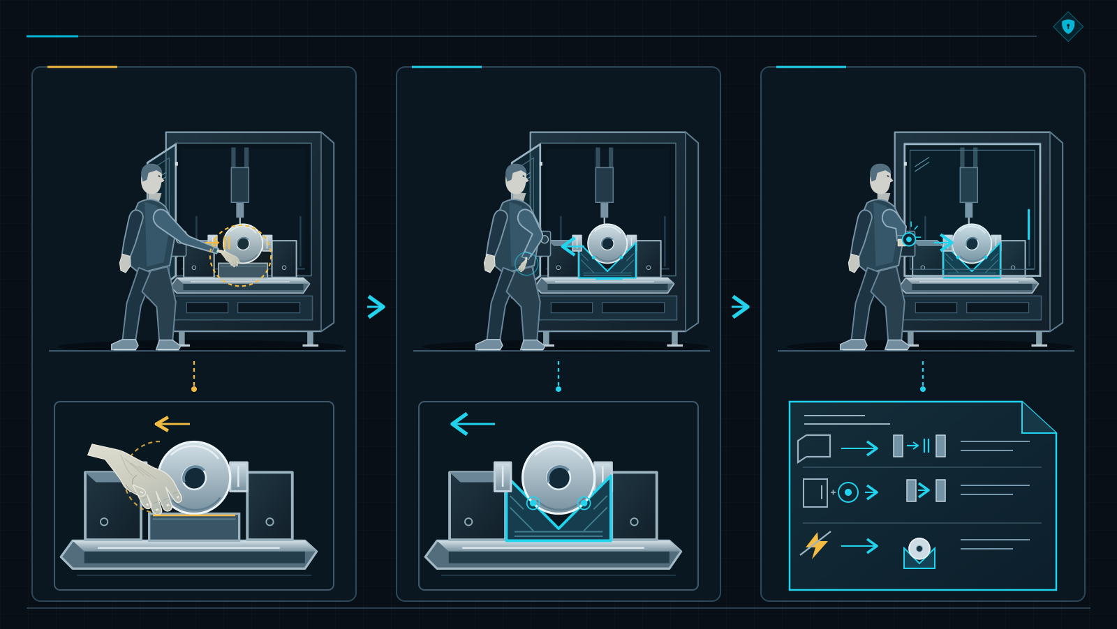
If you skip ISO 12100, you begin ISO 13849-1 without the answers it needs. The risk assessment establishes the required protection. The SRS records the resulting control-system requirements, including PLr. Only then does the designer have a proper starting point.
Movement does not disappear because we call it dangerous
Return to the clamping project. Someone points out that stopping when the guard opens is a proven safety function. Correct. The workpiece still has to be positioned before production can begin.
Standards for specific machine types help break the word “safeguarding” into tasks, movements and conditions. This exposes why one correct control response does not yet protect the whole job.
The clamp must secure the workpiece before machining too
In a machining centre, automatic operation and manual setting are distinct. For both, examine the necessary movements, access to their effects and the required protection. If the tooling needs movement while the guard is open, the design must make that task safe.
Removing the interlock would change the programme. The hand and the jaws would remain in exactly the same place.
For machine tools within its scope, ISO 16090-1 addresses workpiece clamping, monitoring of the clamped condition and conditions for starting operation. The questions therefore go further than the position of the door.
Is the workpiece retained? Which movements may be permitted? What happens when energy is lost? The answers may require a different clamp, a different control method or a completely different clamping sequence.
When a Type-C standard gives a requirement or PLr, retain the application description and its conditions. A letter transfers easily into a spreadsheet. It is harder to notice that it came from a row describing a different access route or machine state.
The SRS must let the next engineer reconstruct the decision: which task the function protects and why that protection is expected. Decide how the workpiece is positioned and clamped before selecting the safety function. Movement during access and retention after energy loss require their own conclusions.
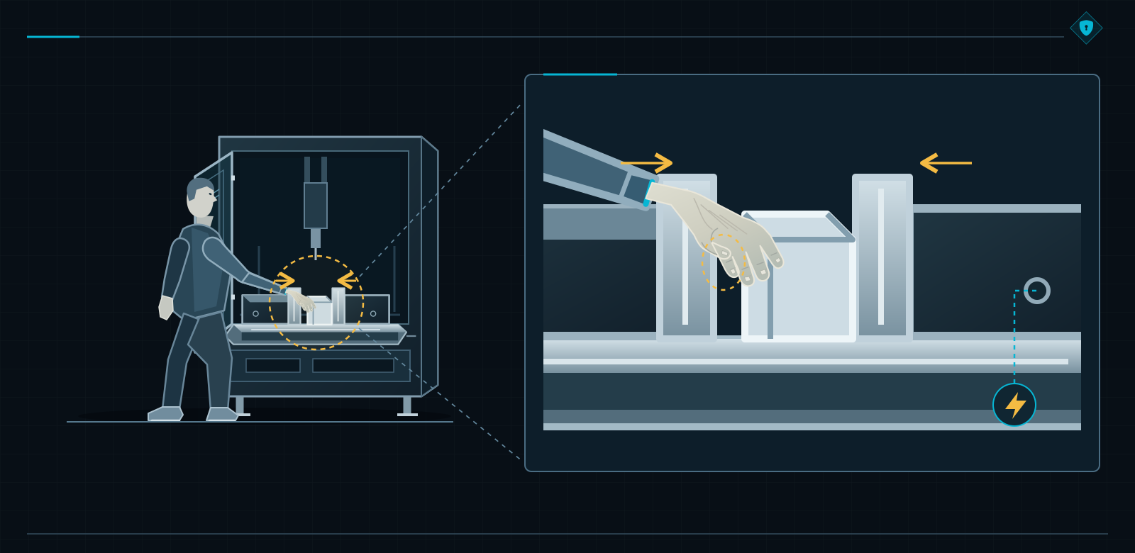
The vertical baling press has finished pressing. The bale still has to be removed
Move to a vertical waste baling press. The designer has considered platen movement during compression. The doors were closed, access was monitored and the cycle has ended.
The operator still has to tie and remove the bale. The operator opens the door, changes position and uses movements needed for removal. In the cycle description, the machine has finished. At the machine, the person is only now completing the job.
EN 16500:2014 gives this phase separate requirements. Its scope concerns specified closed vertical baling presses with manual tying, not every machine used to compact waste.
Clause 5.1.4 addresses bale ejection, controls outside the bale’s overturning area and visibility. Where an open door permits access to hazardous upward platen movement, it specifies two-hand control. Clause 5.2.2 assigns PLr d to that function.
The SRS records the task, movement and protective condition together. The return movement of the ejection mechanism must also be considered. The single word “pressing” does not cover every situation involved in removing the bale.
The cited edition of EN 16500 refers to EN ISO 13849-1:2008. That relationship between editions must be considered when selecting standards. The PLr d from this defined case does not become a universal rating for the entire baling press.
Material still moves through a stopped zone
Now an operator clears a blockage between two machines. Drives in the operator’s zone have stopped. Adjacent equipment continues feeding material through a process opening. The local controller has completed its assigned task.
Material does not recognise supplier boundaries.
ISO 11161:2007 with A1:2010 directs attention to task zones and interfaces in an integrated manufacturing system. Clause 8.1.4 addresses protection where material flows between zones.
Under Clause 8.8.1, the specification includes operating modes, human interactions, system behaviour, interfaces and reactions to faults. Two separate calculation reports leave the integrator responsible for precisely this shared part of the job.
Agree the stopping span or another suitable way of protecting the interface, the access route and the behaviour of adjacent equipment, including what happens when a required signal disappears. A person clearing a blockage needs protection throughout the intervention.
“Interface by the integrator” correctly identifies who owns the task. It does not complete that task in either connected machine. The protective span also depends on hazards transferred by the material flow. The state of one machine must be linked to the required behaviour of neighbouring equipment.
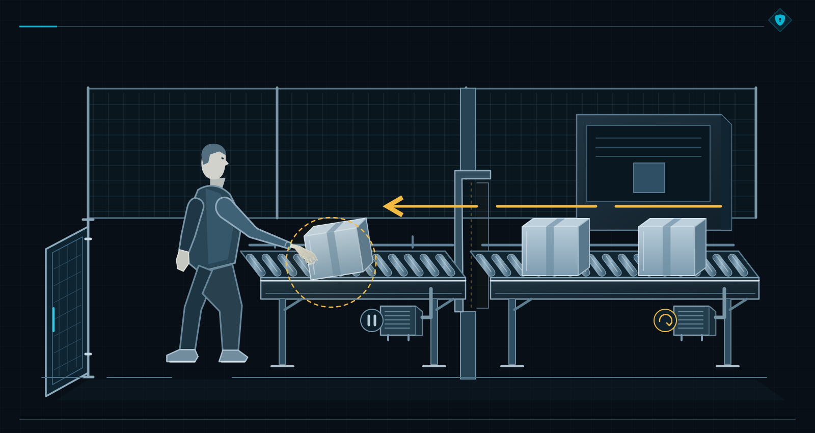
Outside the automatic cycle, people still have work to do. Clamping, bale removal and blockage clearing each bring their own movements, access routes and energy sources. The SRS must carry protection through the whole necessary task.
The clamp has stopped. What must happen to the workpiece?
“The machine must stop when the guard opens.” The control engineer points to the stationary clamp. The mechanical designer looks at the workpiece that the operator is still holding.
Both are looking at the same machine. The word “stop” briefly allowed them to avoid agreeing what must physically happen.
The specification should state the function name, its relationship to the hazard, the initiating event and the response initiated by the outputs. Identify the movements and the protected area. The team can then decide how those movements stop and what state is required afterwards.
Manual positioning during access receives its own requirements, consistent with the selected protective concept. Separately, specify that an open guard in automatic mode must prevent the start of the identified hazardous movements.
Stopping and prevention of unexpected start-up may use common subsystems. Each function still needs a clear description and its own verification. The operator does not stop needing protection when the next command reaches the control system.
Again someone proposes: switch everything off
The idea looks persuasive on the circuit diagram. De-energise the outputs, remove the energy and declare the problem closed. Then the mechanical designer adds one condition: when pressure is lost, the clamp may release the workpiece.
The discussion is no longer only about stopping movement. Load retention and the duration of the required state must also be resolved. An OFF command cannot explain what will support the part after the command has executed.
The SRS describes the physical state required by the risk assessment: specified movements stopped and the workpiece retained where necessary. If there is a gravity-loaded vertical axis, protection against falling must also be included. The design must then show how those requirements are achieved.
Consider loss of supply, unacceptable fluctuations and restoration of energy. Define system behaviour for each condition. Restoring pressure or voltage must not remain an undocumented step in the sequence.
Fault detection needs separate treatment: the reaction leading to a safe state and the period for which that state must be maintained pending repair. Where functions are active simultaneously, priorities and conflicts must be resolved. A stop must not remove necessary load protection without assessment.
The sensor has responded. The mechanics still need time
A person will not wait at the guard for as long as the mechanism finds convenient. The person reaches a particular location. Return to the operator’s position, possible access speed and the time required to achieve the specified state.
The control engineer may show the sensor response time. Logic, communications, actuators and mechanics still have work to do. The SRS needs a requirement for the overall machine response time, including stopping movement.
When positioning protective devices according to ISO 13855, use suitable stopping-performance data and defined assessment conditions. Load, tooling, temperature and wear can change the result. A catalogue parameter is not a measurement of the complete machine.
If the data are missing, record an open action: who will provide them and which decisions depend on the result. A provisional value must later be confirmed or the design changed.
Otherwise, one contractor will build a guard around a number that another engineer regarded as a guess. During acceptance, both may honestly confirm that the stopping time was discussed.
The operator changes mode, then closes the door
The workpiece still needs clamping. If the concept permits movement during access, the SRS defines the operating mode and the conditions for that movement. Mode selection must be unambiguous, and transitions between modes must maintain the necessary protection.
Selecting a mode does not itself start movement. Calling a screen option “service” does not protect anyone at the clamp. Only specified behaviour gives the control engineer an implementable requirement.
Also consider cleaning and repair of the clamp. Some work requires isolation from all energy sources and securing disconnecting devices in the isolated position. Other work requires suitably protected movement. The risk assessment results for those tasks must be reflected in the requirements.
Do not automatically extend the positioning solution to every repair task. A person may occupy a different position and reach different hazards. Renaming the task in an instruction does not change physical access to the mechanism.
After clamping, the operator closes the guard. The sensor confirms the door position. On its own, it does not determine whether someone remains in the zone or whether other protective measures are operating. Those questions become especially important where a second person may be present.
The SRS defines the conditions for reset and restart. Where the risk assessment requires manual reset, locate it outside the hazard zone, with the necessary visibility and without the possibility of actuation from within the zone.
Reset is a deliberate action separate from start. The signal transition must be monitored. Reset itself must not create a hazard, and the relevant safety functions and protective measures must already be effective.
If part of the zone is not visible, use an appropriate measure, such as a reset sequence or presence monitoring. The standard also allows justified automatic reset in suitable cases, including continuous person detection that prevents a hazardous situation.
The document records the decision for the actual application. If reset is itself a safety function, its PLr must also be specified. Buttons with the same label do not necessarily perform the same safety role.
Where a feeder is connected, its supplier needs to know the required state during access to the clamp and the reaction to loss of interface signals. The integrator coordinates the interfaces with the other functions. “STOP sent” describes the sender; the SRS must also define how and when the receiver responds.
One workpiece does not represent the full operating conditions
The operator demonstrated the clamping task once, but it will be repeated throughout the shift. Record the expected demand rate for the safety function and the operating rate of its elements. Access for every part creates different operating demands from an occasional intervention.
Include the environment, cleaning and servicing conditions under which the solution must retain its properties. Relate device data to the actual operating intensity and application conditions, even if the same component is already used elsewhere.
Before closing the SRS, assign every safety function a PLr and record its basis: the risk assessment or an applicable Type-C requirement together with its conditions. For the clamp, the relevant value is the one justified for this application.
The achieved PL will later assess the implementation. At this stage, the team is defining what that implementation must achieve. Similar-looking entries in two spreadsheet columns must not blur the difference between PLr and PL.
Write it so the next control engineer does not have to guess
Assume the team has selected a mechanical locating fixture that supports the workpiece. The operator can place the part and withdraw both hands before closing the guard and starting the clamp. This is one possible arrangement. If the real task still needs movement during open access, that movement requires suitable protection and its own requirements.
The following example records one function. PLr d, 200 ms and the other figures are fictional training data, not machine parameters to copy. A real project must justify each value and apply the correct Type-C requirements. The function sheet remains a working example until those decisions are complete.
| SRS field | Example requirement | ISO 13849-1:2023 |
|---|---|---|
| Function and reason / SF-01, APP-01 | SF-01: stop and prevent powered clamp movement during access to the locating fixture. TASK-L01: position a 12 kg workpiece. HS-01: fingers within the jaw area. Linked risk assessment item: RA-L01. | 5.1; 5.2.1.2; 5.2.1.3 a) |
| Initiating event / REQ-01 | A request for access, or loss of the required closed or locked guard state while clamp movement is enabled. Open access maintains the movement inhibit. | 5.2.1.3 b) |
| Required effect / REQ-02 | Stop jaw movement and prevent further powered movement during access. Do not permit guard unlocking before all required conditions are achieved. The workpiece remains supported by an independent mechanical fixture. | 5.2.1.3 c) |
| PLr and basis / REQ-09 | PLr d — a training assumption assigned in fictional assessment RA-L01. In a real design, the value must come from the project risk assessment or an applicable Type-C requirement. It is not the PL achieved by the control system. | 5.2.1.3 d); 5.3 |
| Time and access / REQ-03 | Up to 200 ms — an illustrative limit from the guard event to cessation of the identified movement, including mechanics. The guard remains locked until all required safety conditions are met. The figure of 200 ms alone does not justify safe access. | 5.2.1.3 e) |
| Operating modes / REQ-04 | Automatic operation and manual loading. This version does not permit powered clamping with the guard open. If the actual task requires it, return to the risk assessment and specify suitable protection. | 5.2.1.3 f) |
| Interfaces / REQ-05 | Confirmation of the required clamp state is only one condition for access. Suitable states of the spindle, axes and feeder are also required and are defined by other functions. Confirmation that a signal was received does not replace the required response. | 5.2.1.3 g) |
| Fault / REQ-06 | A detected fault affecting the function blocks new movement and access permission until the required state is achieved. Maintain that state until the relevant fault is corrected. | 5.2.1.3 h) |
| Energy / REQ-07 | Loss and restoration of energy must not cause hazardous movement or release of the supported workpiece. The mechanical fixture requires separate justification; it is not assigned a PLr merely because it appears in this sheet. | 5.2.1.3 i) |
| Demand rate and environment / APP-02, APP-04 | Example: 40 accesses per hour, 16 hours per day and 250 days per year, giving 160,000 demands per year. Element operations are recorded separately. Indoor use at 5–40°C with coolant and swarf is assumed; other conditions require assessment. | 5.2.1.2; 5.2.1.3 j) |
| Priority / REQ-10 | The safety-function demand has priority over a normal clamp START. Interaction with other functions must not remove workpiece retention or permit premature access. | 5.2.1.3 k) |
| Type-C standard / APP-03 | Check the scope and requirements concerning clamping and access. For this hypothetical machine tool, ISO 16090-1 is considered. Exact clauses and the result of applying them must be recorded before closing the SRS. | 5.2.1.3 l) |
| Return to operation / REQ-08 | After restoring the required states, use a separate deliberate reset and a separate start command in accordance with the selected solution. Closing the guard, resetting or restoring power must not start the clamp. | 5.2.1.3 m) |
| Verification and version | Link REQ-01 to REQ-10 with the relevant analyses, tests VT-01 to VT-06, design records and assessed configuration. PL and priority evaluations need their own evidence. Results remain incomplete until verified. A change to the workpiece, mode or parameters requires an impact assessment. | 5.4; 10; 12 a) |
A single function sheet is only one part of the SRS. The complete record also includes machine limits, human tasks, risk assessment inputs, other functions, interfaces and document control. Every “not applicable” entry needs a reason.
Keep unresolved matters visible. A missing PLr or access condition does not become complete because someone signs the bottom of a finished form.
The SafetySoftware PDF contains the worked SF-01 example, test criteria and fillable project, function and evidence sheets. Use it to record your own decisions; the example values are fictional.
Download the SRS worked example and fillable templates (PDF, English)
The mechanical designer and the control engineer need the same decisions. Give requirements identifiers, versions and links to the risk assessment. Later, connect them to the design and verification evidence.
The information may be managed in a document, individual sheets or a controlled register. ISO 13849-1 requires the content; it does not impose one mandatory table format.
Structured this way, the SRS supports design under Clause 5.2.1.1, covers the applicable content of Clause 5.2.1.3 and forms part of the technical documentation identified in Clause 12 a). It also allows work to pass from the risk assessment team to the control-system designer without relying on meeting-room memory.
Users and integrators receive the information needed for their tasks. That does not automatically require disclosure of every internal design record. The scope of supplied information must reflect the relevant obligations and application.
When the control engineer returns to the software, the requirements refer to the same hand, clamp and sequence of states. If the clamp changes, the reason for those requirements can still be reconstructed.
Now build what the SRS requires
The team knows how the operator positions the workpiece, which movements are required and what must happen when energy is lost. The safety functions have their PLr. Someone may now announce that safety has been dealt with.
So far, the team has agreed what must be done. The machine does not yet do it.
Select the architecture and subsystems, develop the logic and set the parameters. Check loads, diagnostics, environmental conditions and mechanical interaction. The valve must bring the system to the required state, and the drive function must correspond to the actual movement.
The clamp must also be manufactured and checked. Its geometry must support the selected loading method. Correct software cannot replace a mechanical part that was supposed to retain the workpiece without the operator’s hand.
Previously validated subsystems can save time. ISO 13849-1 allows their use when the integration conditions are satisfied. Retain their application data and limitations, then justify the complete safety function as integrated.
This is the right time to use proven building blocks: the requirement is known, so the properties expected from each block are clear. The team can also identify what still needs to be demonstrated after installation.
When evaluating achieved PL according to ISO 13849-1, examine its relationship to PLr, reliability, architecture, diagnostics and common-cause failures. Systematic failures, software, environmental conditions and ergonomics also matter.
The programme can still permit movement in the wrong mode. The reliability model may remain perfectly calculated while the error sits in the movement-permission logic. That exact condition must be found and tested.
Likewise, a fault exclusion needs a basis that remains valid in the real installation and during use. Calculation software will not inspect a clamp altered on the workshop floor. Someone must supply truthful assumptions to the model.
The declaration must be backed by all the completed work
The SRS alone is not enough to declare full conformity with ISO 13849-1. The applicable design, verification, validation and documentation activities must all be completed.
A standard number is quick to type. The work represented by that number takes more than one line in a declaration.
The absence of ISO 12100 from a list of standards does not, by itself, prove that the risk assessment was omitted. Its content, decisions and use in the design provide the evidence. Conversely, an instruction to “make it PL d” without a task and protective objective still lacks essential inputs.
After implementing the solution, return to the risk assessment for the complete machine. Confirm that the intended risk reduction was achieved without introducing new hazards.
A revised clamp may retain the workpiece better but require a different removal method. Analyse that next task too. The iterative ISO 12100 process returns to the real machine instead of ending at the corrected drawing.
The SRS starts work that must later be demonstrated. Selection, integration, PL evaluation, verification and validation must prove that the implemented function meets its requirements under the intended conditions. The document cannot do that work by itself.
The machine has stopped. The test is not over
Open the guard again. This time the required stopped movements, response time and workpiece-retention state are known. The controller reports the expected status. The person conducting the test also watches the mechanism.
Confirm movement, load behaviour, retention and return to operation. Relate each effect to a specific requirement. A message on the display does not describe the result of the complete test.
This work began before the machine was built. Clause 5.4 requires the SRS to be reviewed before design: do the functions correspond to the risk assessment, and does the specification contain the necessary requirements?
Validation of the SRS under Clause 10.2 helps identify omissions, errors and inconsistencies with the application, operating conditions and reasonably foreseeable misuse. Finding a missing task is much easier while the clamp still exists only on a drawing.
Validation of the implementation confirms compliance with the SRS and other applicable requirements. It uses analyses and tests conducted according to a plan. Analysis can begin alongside design; final testing on the physical machine closes the relevant part of the process.
Test the movement the operator actually needs
At the guard, test initiation, response, timing and maintenance of the required state. Then move to workpiece positioning. If the SRS permits movement during access, test it under those exact conditions.
Continue through mode selection, completion of the task, reset and restart. The operator must be able to follow the complete agreed workflow. One successful opening of the door does not reproduce what happens over repeated production cycles.
On an integrated line, observe the second machine too. Confirmation that its controller received a signal is part of the test, not the final result. Demonstrate the required state of the connected system, including delays and interactions.
Separate supplier protocols will not stop material at the interface. That behaviour must be tested across the agreed integration scope.
The plan also covers suitable analysis and tests for faults, signal loss and supply changes. The required scope follows from the standard and the design. Tests need prepared, controlled conditions and protection for the competent people carrying them out.
For the clamp, workpiece retention after interruption of normal operation returns as a test criterion. Stopping movement and retaining the load must meet in one result, not two unrelated descriptions.
Record the test condition, criterion, result and machine configuration. For time measurements, record the method and conditions too. The next engineer needs to know which load was tested and what behaviour was accepted.
A signature under “function works” takes less space. Unfortunately, it leaves far more work for the next designer.
The software has changed. The test report still remembers the old version
The control engineer changes the movement-permission condition, but the test plan still checks the previous one. Both documents may be closed even though they describe different configurations. The requirement, design and evidence must refer to the same assessed version.
Trace the change from the SRS to the relevant results and assess its effect on other functions. A correction at the clamp does not disappear from the evaluation merely because it is already in the programme.
The standard recommends that people validating the SRP/CS are independent from its design. Someone outside the design team is more likely to challenge an assumption that the author has stopped noticing. Competence, a suitable process and documented results matching the evaluation scope are still required.
This does not create a general requirement for external certification of every safety function. What has been demonstrated depends on the work performed and its scope.
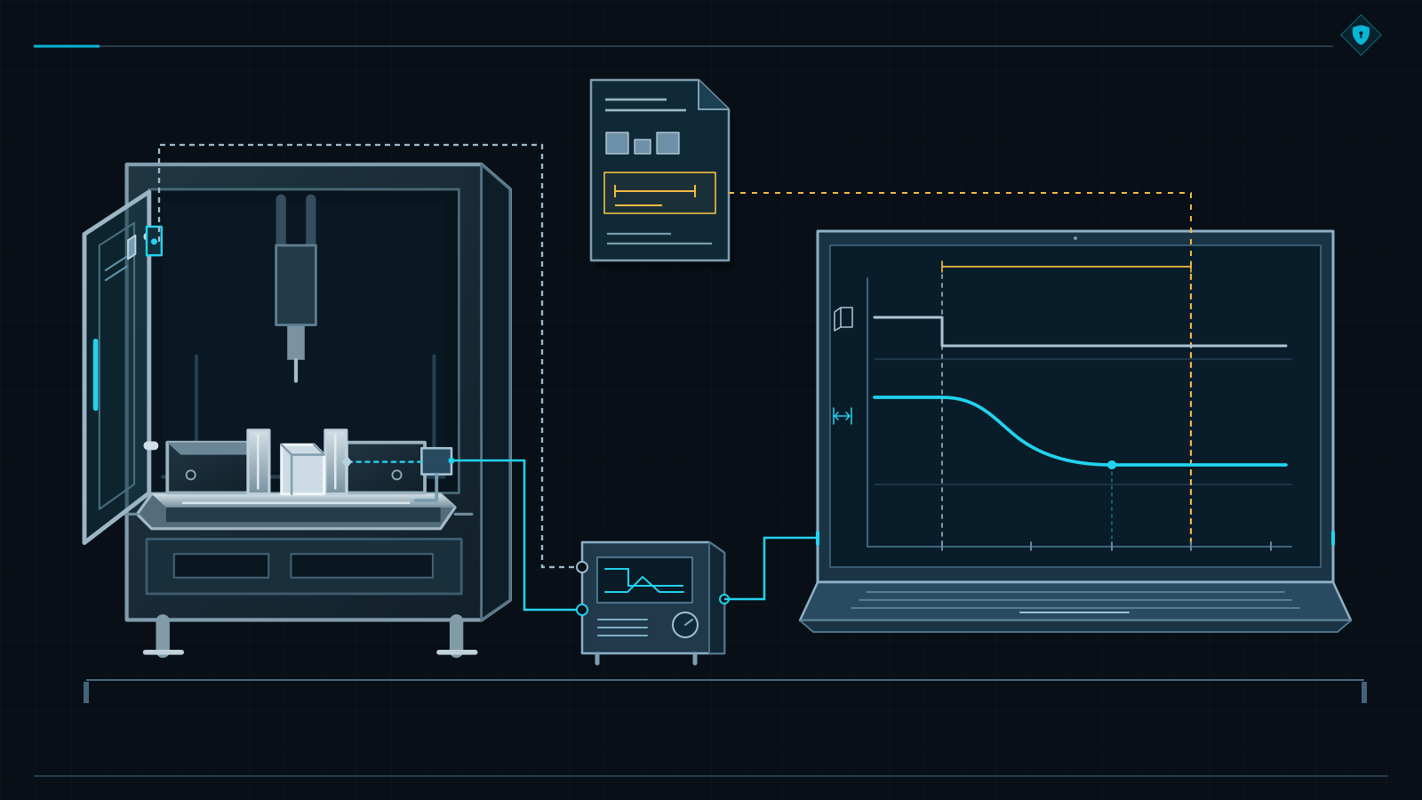
A larger workpiece arrives several months later
The larger workpiece fits on the table, and the clamp closes around it. Someone says the familiar words: “The machine can do it.” Before allowing movement, return to the machine limits.
Clause 5.3 of ISO 12100 covers limits of use, space limits, time limits and other limits. For this workstation, examine the intended workpieces and tools, loads, clamping method and space required by the operator. Table dimensions alone do not define permissible use.
If the new task remains within the assessed limits, it may be an intended changeover. Confirm that the protective conditions remain satisfied for that configuration. A larger workpiece does not automatically mean the machine has been rebuilt.
But suppose the operator must now approach from the opposite side, which is not visible from the reset position. Or a new tool increases stopping time beyond the value used when designing the protection. Something on which the protective effectiveness depended has changed.
Not one module in the cabinet has been replaced. The component list therefore looks reassuring. It never recorded the direction from which the operator puts a hand into the machine.
Return to the limits and risk assessment, then to the requirements in the SRS. Evaluate the effect on the design and existing evidence. Permit the new task only after implementing the necessary protection and completing the required verification and validation.
Adding the larger workpiece to the documentation does not, by itself, justify extending the machine’s intended use.
The same principle applies to conditions needed to maintain protection. If effectiveness depends on inspection, adjustment, replacement of a component or a specified period of use, that information must reach the people performing those tasks. Time limits do not end at commissioning.
For servicing, an SRS linked to the risk assessment and design documentation makes the original decisions recoverable. Without it, the team is left calling the person who wrote the software years earlier and hoping that the assumptions are still remembered.
A conversion needed for a new use may also amount to a substantial modification. A larger workpiece or departure from previous limits does not decide that question by itself. The legal criteria apply to the modification actually made.
Regulation (EU) 2023/1230 defines substantial modification in Article 3(16) and sets out the obligations of the person carrying it out in Article 18. Those provisions apply from 20 January 2027. Updating the SRS is only one part of the work that such a modification may trigger.
During acceptance, test what the SRS promised. Test the movements, energy states, access routes and interfaces used by people. When the task or operating conditions change, assess whether the existing protection and its justification remain valid.
Before you order the next control package
Return to the operator holding the workpiece. Walking through one task revealed a gap that appeared neither in the device catalogue nor in the PL report. The tooling, access, movements and behaviour after energy loss had to be agreed.
Those decisions created a real design assignment. The control solution can now be selected and checked against the protection actually needed. Certificates and calculations finally have something meaningful to support.
On the next machine, walk through the process with someone who knows the workstation. Find the task and hazards in the risk assessment, the requirements in the SRS, and the answers in the design and verification evidence. That trail shows exactly where the justification breaks.
And when someone standing beside a completed cabinet asks whether safety is already finished, show how the operator is expected to clamp the workpiece and what protects the hand during that task. It usually shortens a component-only discussion very effectively.
Sources and scope of the examples
The examples are based on the editions and clauses listed below. They illustrate how to formulate requirements; every machine project must establish which standards and provisions fall within its actual scope.
- ISO 13849-1:2023 , Safety of machinery — Safety-related parts of control systems — Part 1: General principles for design : Clauses 4.1–4.6 and 5.1–5.4, including 5.2.1.3 and 5.2.2–5.2.3, and Clauses 6–10 and 12–13.
- ISO 12100:2010, Safety of machinery — General principles for design — Risk assessment and risk reduction : Clauses 4–6, particularly 5.3–5.4.
- ISO 16090-1:2022 , Machine tools safety — Machining centres, milling machines, transfer machines — Part 1: Safety requirements : Clause 5.2.5.5 on workpiece clamping.
- EN 16500:2014 , Machines for compacting waste materials or recyclable fractions — Vertical baling presses — Safety requirements : Clauses 5.1.4 and 5.2.2. Its scope covers specified closed vertical baling presses with manual tying. The cited requirements refer to EN ISO 13849-1:2008.
- ISO 11161:2007 with Amd 1:2010, Safety of machinery — Integrated manufacturing systems — Basic requirements : Clauses 7.1–7.2, 8.1.4 and 8.8–8.10. The example concerns tasks, interfaces and protective span in an integrated manufacturing system.
- ISO 13855:2024, Safety of machinery — Positioning of safeguards with respect to the approach of the human body : Annexes B and D, including stopping-performance data and assessment conditions.
- Regulation (EU) 2023/1230 of the European Parliament and of the Council on machinery : Article 3(16), definition of substantial modification; Article 18, obligations of the person carrying out a substantial modification; and Article 54, dates of application.