
The most hazardous decisions in machinery safety are the ones made with the assumption that the matter has been finally and permanently “sorted”.
A hazard shows up during a project. Someone suggests a fast fix: add a guard, install a light curtain, implement a safety function in the control system. It feels like the issue is closed. A protective measure appears in the file, the value in the risk assessment table drops, and the team moves on.
And then it turns out that:
- a heavy guard has created a new crushing or trapping zone,
- the interlock restricts access for set-up/adjustment and encourages bypassing,
- the protective device was positioned without any practical verification of stopping time,
- an additional element in the safety-related circuit has changed the system dynamics in a way nobody assessed.
These are not mistakes caused by ignorance.
They are mistakes caused by oversimplification.
A protective measure is a design change. It alters the machine geometry, the available space, the way the machine is operated, the sequence of actions during a fault or jam, the behaviour of the drive system, and the control system response. Every such change affects the hazard profile—sometimes obviously, sometimes in very subtle ways.
In industrial practice, linear thinking is common: there was hazard A → we added safeguarding → hazard A “disappeared”. In reality, the system is not linear. A change in one area can shift risk into other, less visible parts of the machine and its use.
That is exactly the point—when safeguarding, instead of stabilising the system, introduces new technical tensions—where a calm, engineering-led analysis is required.
The first mistake that often follows “adding safeguarding” is treating the change as purely local—assuming it addresses only one hazard and has no effect on the rest of the machine.
In practice, every protective measure interferes with the machine design or its control system. That means it also affects:
- kinematics,
- access to the working area,
- response times,
- how adjustments and maintenance tasks are carried out,
- how the machine is handled during disturbances and faults.
If these changes aren’t assessed as a whole, it’s very easy to end up with risk being shifted rather than reduced.
1. A guard can introduce new mechanical hazards
The most straightforward example is a fixed or movable mechanical guard. Its purpose is clear: prevent access to the hazardous area. And in many cases it does exactly that.
The issue starts when the design focuses only on separation, while overlooking the physical characteristics of the guard itself.
A heavy hinged guard adds mass.
Added mass means stored potential energy.
Stored potential energy means the possibility of dropping, crushing, or impact.
If the guard’s movement path, support method, and stability in both the open and closed positions haven’t been assessed, the protective measure becomes another moving part of the system. And it creates its own hazardous zones.
In practice it can be very mundane: an operator opens the guard, holds it with one hand, reaches inside with the other, and someone brushes past and knocks it. Or, after a year of service, the hinge develops play. At that point the guard stops acting as a “barrier” and starts behaving like a dynamic component.
This isn’t an edge case.
It’s the predictable result of ignoring that a protective measure can itself be a source of energy and motion.
2. A safeguarding device without verification of safety performance
A common pattern in the field is: install a light curtain, wire it into the safety controller, set the distance “as per the catalogue,” and consider the matter closed.
But simply fitting a safeguarding device is not, by itself, evidence of effective risk reduction.
To claim real effectiveness, at least three technical conditions have to be met.
a) Confirm the actual stopping time
The separation distance between the safeguarding device and the hazard zone cannot be set “based on experience.” It must come from calculations in line with ISO 13855, which are based on:
- the machine’s actual stopping time (including system inertia),
- the response time of the safeguarding device and the control system,
- human reaction time,
- fixed geometric constraints determined by the type of device.
The key word is: actual.
Stopping time should be established by measurement under representative worst-case conditions: at maximum load, at the highest speed, and allowing for changes over time (wear of braking components, tolerances, temperature). Not a catalogue figure. Not a declared value. Not a “typical” time.
If that measurement has not been performed, there is no evidence that the safety distance has been selected correctly. And without a correct safety distance, there is no evidence that the protective device truly prevents access to the hazard zone before the hazardous movement has come to a stop.
In that case the safeguard may be logically correct, yet physically ineffective.
b) Verification of the safety function and Performance Level
The second element is verification of the safety function in accordance with ISO 13849-1.
A protective device is only one part of the chain. The safety function comprises:
- the sensor (e.g. a light curtain),
- the logic subsystem (safety controller, safety relays),
- the final elements (contactors, valves, drives),
- the architectural structure (category),
- reliability parameters (MTTFd, DC, CCF).
If the Performance Level has not been calculated and it has not been demonstrated that the achieved PL ≥ required PLr derived from the risk assessment, then formally there is no confirmation that the safety function delivers the required level of risk reduction.
A common mistake is to assume: “the light curtain is PL e, so we’re safe”.
It is not the light curtain alone that must meet the required level.
It is the complete safety function that must achieve it.
If the stop chain includes an element with insufficient reliability, a single contactor without monitoring, or diagnostic coverage is missing, the actual PL may be lower than required. In that case, the effectiveness of the protective measure is an assumption, not a demonstrated fact.
c) Functional consistency — not only electrical
The third area is integrating the safety function with the production process.
Even a correctly calculated separation distance and a properly confirmed Performance Level do not ensure effective protection if:
- the reset can be initiated from a position that still allows access to the hazard zone,
- restart occurs automatically once the safeguarding device is cleared,
- transient conditions have not been considered (e.g. residual motion, axis inertia),
- behaviour under a partial system fault has not been validated.
A safety function must not only be “wired in”; it must be logically correct and validated across the full machine operating scenario.
If any of these elements (stopping time, distance per ISO 13855, PL/PLr per ISO 13849-1, reset and restart logic) has not been robustly verified, there is no evidence that the risk has been effectively reduced.
And the issue goes further.
In that situation, it is not only that the effectiveness of the protective measure has not been demonstrated. At this stage, new hazardous situations are being introduced. The operator receives the message that the area is safeguarded. Behaviour changes—approach becomes faster, the distance reduces, and actions become more decisive. If, however, the actual stopping time is longer than assumed in the design, a situation can arise in which a person enters the hazard’s zone of influence before the dangerous movement has come to a stop.
This is a standards-based hazardous situation: a circumstance in which a person is exposed to at least one hazard.
The same applies where the Performance Level has been inadequately validated: if the safety function does not achieve the required PLr, then under a single fault condition or loss of diagnostics the stop function may be lost. In that case, we are dealing with a situation where:
- the hazard is still present,
- the person assumes it has been reduced,
- and the system does not deliver the safety function as intended.
This is not “incomplete paperwork”.
It is a structurally new hazardous situation created at the design stage.
3. When safeguarding changes the way work is done—and, with it, the structure of risk
Every protective measure changes more than the machine’s geometry or stopping performance. It also changes how the task is carried out in practice.
This is exactly where new hazardous situations are most often created—not because the safeguarding device “doesn’t work”, but because the design did not anticipate how it would actually be used in day-to-day operation.
a) Restricted access = improvised intervention
If a guard significantly restricts access for adjustment, cleaning, or changeover, operators start shortening the intended procedure:
- leaving the guard partially open,
- defeating the limit switch,
- carrying out tasks while residual movement is still present,
- intervening when the stop condition is not reliably achieved.
This is not a “lack of discipline” issue.
It is the consequence of a design that did not account for the real frequency and practical nature of the task.
At that point, a hazardous situation emerges: a person is in an area that was assumed to be inaccessible during motion, and the system is no longer able to enforce safe conditions.
The safeguard has not been removed.
The bypass has effectively become built into the way the job is done.
b) Safeguarding that disrupts the work sequence
Every safety function introduces logical conditions, for example:
- a stop on infringement,
- start interlocking (start prevention),
- reset,
- confirmation of initial conditions.
If the return-to-operation sequence is too complex, illogical, or unclear, the likelihood increases that people will act outside the assumed operating scenario.
For example:
- reset being performed without a visual check of the hazard zone,
- restart while residual movement is still present,
- intervention in service mode without full isolation of energy.
Each of these situations constitutes a hazardous situation: a person is within the hazard zone while the required safety conditions are not met.
From a risk assessment perspective, this is not “operator error”.
It indicates that the impact of the protective measure on the system’s behaviour and dynamics was not properly analysed.
c) Conflict between safety and ergonomics
If a protective measure:
- restricts visibility of the working area,
- forces awkward or unnatural body postures,
- increases physical effort,
- extends cycle time in a way that materially affects operations,
it increases the likelihood of undesirable behaviours.
And likelihood is one of the two elements in the definition of risk.
In practice, it often looks like this:
The design assumes safe access with the guard closed.
The operator, to see the part, leans in and reaches a hand under the lower edge.
The guard is physically present.
The hazardous situation still occurs.
The safeguarding did not eliminate the risk.
It changed the way the risk is realised.
4. Linear thinking versus systems-based analysis
All of the cases described share the same root cause: a linear approach to risk reduction.
Hazard → protective measure → problem solved.
In reality, any design change to a technical system should be treated as a new system configuration.
A new configuration means:
- new operating conditions,
- new access points,
- new movement paths,
- new disturbance or fault scenarios,
- new hazardous situations.
If the design process does not loop back to hazard identification after a protective measure is introduced, the assessment is not robust—even if the paperwork looks complete.
That is the key distinction between “having a safeguard” and achieving genuine risk reduction.
5. Why inherently safe design solutions are more stable
A clear pattern shows up when you look objectively at how design errors arise: most issues occur when safety is “added on” rather than engineered in from the start.
Inherently safe design measures behave differently from protective measures. They do not simply restrict access to a hazard; they reduce or remove the hazard at source.
Typical examples are straightforward:
- reducing kinetic energy by limiting speed or mass,
- limiting torque to a level that remains safe in the event of a collision,
- reducing clamping/pressing force,
- rounding edges instead of relying on guards to cover them,
- changing geometry to eliminate a crushing/pinch point,
- using a drive with a controlled stopping characteristic.
In these cases the risk reduces because the energy available in a dangerous event is reduced, or the mechanism by which it is released is removed altogether.
This is a qualitatively different type of reduction than simply installing a barrier.
When you reduce speed, you reduce energy across every scenario.
When you reduce force, you reduce the potential severity of harm.
When you eliminate a pinch point through geometry, that specific harm mechanism no longer exists.
In many situations this avoids having to “build” safety through additional control logic, resets, and complex sequences. The risk decreases structurally.
That is why these solutions are inherently more stable.
6. Can inherently safe design solutions create new hazardous situations?
It can. But the mechanism is different—and typically less common.
Example: reducing speed or force in a process can increase the number of disturbances (slip, part movement, more frequent jams). The result is more manual intervention. And an increase in intervention means more moments where a person enters hazard influence zones—creating new hazardous situations.
This is not a direct “side effect” of the design itself.
It is a consequence of changing process stability and the frequency of human interaction.
The key difference is that inherently safer design changes the energy source or the geometry, not merely access. That is why the number of new hazardous situations is usually lower than with add-on (secondary) protective measures.
7. The fundamental difference
A protective measure says:
“The hazard exists; we will restrict access to it.”
An inherently safer solution says:
“We will change the hazard—or remove it.”
The first approach creates constraints and conditions.
The second changes the physics of the system.
That is why, in practical design work, the safest route is to start with reducing energy, changing geometry, and eliminating the hazard mechanism, and only then—if necessary—apply technical and supplementary protective measures.
This is not a matter of philosophy.
It is a matter of stability.
8. New hazards are part of the process. They must not be ignored.
The main issue with so-called “secondary risks” is that they are treated as insignificant—like a minor inconvenience after implementing a safeguard, or something that can be “tidied up later.”
From a risk assessment perspective, this is not a detail.
It is a critical point in the process.
Every protective measure changes the system configuration. And any configuration change creates the potential for new hazardous situations.
If, after risk reduction, you do not return to hazard identification, the process has been interrupted. It is not complete—it has been left open.
In practice, this is exactly where the gap appears: hazard A has been formally reduced, but hazard B emerges—less obvious, harder to spot, and often tied to operation, reset, access, and the dynamics of stopping.
If you skip this step, your risk reduction is only partial.
9. The iteration you can’t just “click through”
That’s why, in a properly designed risk reduction process, one question should be asked after every step:
Have the protective measures introduced a new hazard?
If the answer is “yes” — the analysis goes back to hazard identification.
If the answer is “no” — that must be a conscious decision, not an automatic “next”.
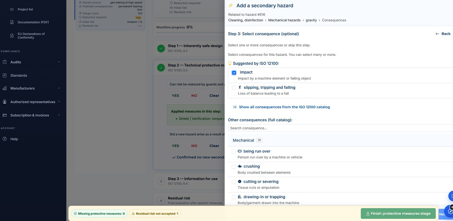
This is exactly the mechanism SafetySoftware.eu enforces explicitly: after the risk reduction step, the system requires a decision on whether the implemented protective measures have generated new hazards. It won’t let you proceed without taking a position.
This isn’t a cosmetic feature.
It’s a safeguard against turning the process into a linear, oversimplified checklist.
Because the biggest mistakes don’t come from having no guards.
They come from failing to iterate.
And machinery safety starts precisely where the thinking stops: “we added a safeguard, so we’re safe.”