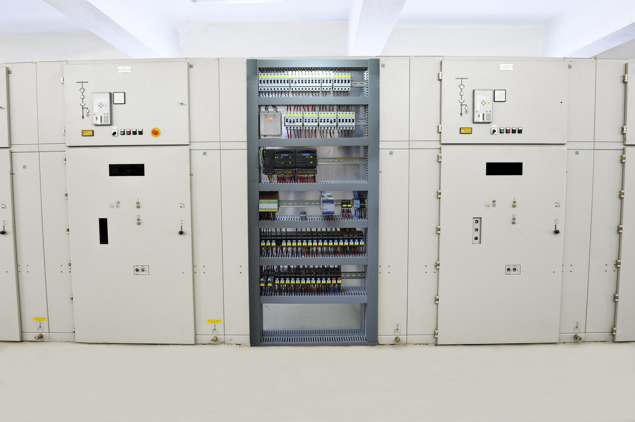

“Set the second one differently.” Two identical lines make the same product, yet need different temperature settings. An experienced operator knows what to adjust. A new operator must be shown. Ask why identical machines behave differently and the answer is usually that every machine has its own personality.
That is how a disturbed measurement stops being a fault requiring repair. It becomes practical knowledge handed from one shift to the next. The process engineer corrects the parameters, the operator watches the result, and production points out that the line still runs. Instead of repairing the installation, the business raises the demands placed on its people.
This is one of the less spectacular consequences of EN 60204-1 electrical mistakes. Nothing has to burn. No protective device has to trip. Poor cable routing can quietly make a plant pay every day for extra adjustment, checking and process correction. The cost disappears into labour time, so it is easily mistaken for a normal production expense.
This has far more to do with the electrical equipment of machines than neat-looking cable trunking inside an enclosure. An electrical fault can change how an entire machine is used. If it forces more frequent access to a hazardous area, it also undermines the assumptions behind the risk assessment. Adjustment once a month and adjustment every hour are materially different, even when both appear under the same word in the documentation.
Other plant myths follow the same career path. Red on the signal tower must indicate every stoppage because the manager wants to see where production has stopped. RCDs are not used with variable speed drives because they caused trouble once. Nobody asks about the supply system because the voltage is correct and the protective conductor is connected.
Each explanation closes an awkward conversation quickly. In time, asking for the technical basis starts to sound like inexperience. Real experience is needed for exactly the opposite reason: to distinguish a proven solution from an error that everyone has merely learned to operate around. A standard number in the documentation will not settle that question. You must inspect the installation, trace how the protection works and watch what people actually do at the machine, especially what the machine was never supposed to demand from them.
The hardest fault to remove is the one that has already become company policy.
1. The process engineer regulates a process the installation keeps disturbing
The process engineer is told to stabilise the second line. They receive temperature readings, production results and permission to alter parameters. From that information they select settings that deliver the required product. If the settings need correction, they correct them.
The real cause, however, is the routing of thermocouple conductors beside the motor cables of servo drives. Disturbance enters the thermocouple circuit and appears on the operator panel as temperature. The same product needs different settings not because somebody discovered a new property of the material, but because one line has a worse electrical installation.
The process department has been handed a problem that the electrician did not leave on the schematic. The error was left in the cable tray.
The controller receives a false measurement and responds to it diligently
A thermocouple produces a small voltage that is converted into temperature using the sensor characteristic and cold-junction temperature. If disturbance corrupts the reading, the controller works from false information. It may increase or reduce heating exactly as its algorithm requires even though the real temperature gives no reason for that response.
The measurement problem now changes the process itself. A person observes the outcome and tries to compensate through the settings. The supposedly automatic line gains another control loop that was never listed in the purchase specification. Automation regulates against a false measurement. The process engineer corrects the automation. In the equipment schedule, the first controller appears as a device and the second as a salary.
A plausible number on a screen proves very little. A disturbed reading may remain comfortably within the measurement range. There may be no open-thermocouple alarm or other message clearly directing maintenance towards the installation.
Identical schematics do not rule out different behaviour either. A schematic shows connections. The physical proximity of conductors, termination of screens and quality of protective bonding must be checked on the machine.
“But the standard allows them to be routed together”
It does. Subject to conditions. Clause 13.1.3 allows conductors from different circuits to run beside one another, in a common duct and, in defined cases, within common assemblies. The condition is that the arrangement must not impair the proper functioning of any circuit. Requirements for separation or insulation where different voltages are present come in addition to that condition.
The reply “the insulation is rated for the voltage” therefore answers only part of the question. Conductors do not have to short together for the installation to be wrong. It is enough for one circuit to corrupt information needed by another.
EMC requirements concern both disturbance emission and the immunity of equipment in its intended operating environment. Informative Annex H develops practical measures: separating power and signal conductors, applying screens correctly, providing suitable bonding and using cables in line with manufacturers’ instructions. Buying screened cable does not make EMC disappear from the job. The cable still has to be routed and terminated correctly.
First check whether the temperature actually changed
Before changing the recipe again, challenge what everyone has treated as certain: the credibility of the indication. Compare the displayed value with an independent reference measurement, allowing for measurement position and sensor response time. At the same time, record drive operation.
Look for a relationship between drive activity and deviation of the indication, not merely between drive activity and the temperature profile. Machine movement may genuinely affect the process. Check the input configuration and the complete measurement chain. Then use a controlled test to assess the effect of changing the route, screening or bonding. Do not alter the recipe at the same time, because that destroys the ability to separate causes.
If disturbance is responsible, a separate setting for the second line does not prove that the process has been engineered correctly. It proves only that somebody found a way to produce despite a measurement error. The next change in conditions may demand another intervention.
The disturbance now has its own process setting. It can be reproduced whenever the recipe is loaded.
2. Once a month in the risk assessment, once an hour in production
“Adjustment was covered by the risk assessment.” It was. Once a month. The operator now performs it every hour because the process will not hold its parameters without repeated correction. The task has the same name, so the paperwork appears consistent.
Consider a version in which the intervention requires access behind a guard, close to hot process components. The extra servicing then means extra exposure. The machine does not even have to permit movement with the guard open for this to become a safety issue. It was intended to need occasional adjustment. It now requires regular production rescue. The risk assessment still grants it the assumptions belonging to the first version.
“It is only a process sensor”
That is one way to try to separate the measurement problem from safety. The sensor does not perform a safety function. The relay works. Opening the guard stops the drives. Therefore, the fault supposedly affects quality only.
But the false measurement is precisely what brings a person to the machine more often than intended. An ordinary process sensor does not have to control a safeguard for its failure to undermine the conditions on which that safeguard was selected.
ISO 12100 links equipment reliability with reducing the number of interventions and the resulting exposure to hazards. That link expressly includes functions other than safety functions. Dividing equipment in the documentation into “safety” and “process” does not remove the need to trace the consequences of how it behaves.
In this example, the electrician left a disturbed measurement circuit. The process engineer found settings that allow production. The operator performs additional tasks. Every department dealt with its own section. Only exposure frequency has no department of its own, which is why it so easily loses its owner.
If the argument for adequate risk reduction relied on sporadic access, that argument cannot remain current after intervention becomes hourly. This is not about entering a new review date. The information on which the conclusion was based has changed.
| Assumption used in the assessment | Actual work in the scenario | What must be reassessed? |
|---|---|---|
| Adjustment once a month | Intervention every hour | Frequency of exposure to the hazard |
| One short task during a planned stop | Repeated corrections and checks until the required result is achieved | Total exposure time and the conditions in which the task is performed |
| A fixed guard removed only occasionally | Access needed several times during a shift | Whether the protective measure matches the real need for access |
This cannot be converted using a simple multiplier. More frequent adjustment does not automatically produce a predetermined increase in risk scoring. You must establish what the person does, which hazards are present, how long exposure lasts and what protection remains effective.
Leaving the old frequency unchanged, however, means knowingly assessing conditions other than those at the workstation.
A guard selected for maintenance is now serving production
Suppose infrequent access justified a fixed guard. For a monthly task, removing it, completing the work and refitting it fitted the maintenance arrangements. Now the same operation must be repeated throughout the shift. Eventually somebody leaves the guard unsecured.
The plant discovers a new problem: incorrect employee behaviour. The cable tray stays exactly as it was. The operator gets another training session.
That does not excuse working without protection. It shows where the causal analysis was cut short. ISO 12100 draws attention to the connection between a growing need for access and fixed guards not being replaced. In those conditions, another suitable protective solution may be needed. Regularly removing the guard cannot be treated purely as a disciplinary issue.
It would be equally absurd to leave the defective measurement in place and focus only on making the machine easier to open. First remove the cause of unnecessary intervention. Then select protection for the tasks that genuinely remain necessary. As long as the fault exists, the assessment and the protective measures must address current working conditions, not the promise of a future repair.
After correcting the installation, do not check only whether the indication is stable. Check whether the constant corrections have actually stopped. Only then can you confirm which assumptions about operation once again match the machine.
A risk assessment written for occasional adjustment is not an alibi for a machine that demands intervention throughout the shift.
3. Red, because the manager dislikes stoppages
“When the machine stops, it must show red. I want to see immediately where production is down.” The automation engineer receives a clear requirement. Link the signal to the absence of automatic operation. Batch complete: red. Waiting for material: red. Hazardous condition: also red.
The signal tower reports the manager’s dissatisfaction flawlessly. Its message to the operator is less successful.
One colour, conflicting instructions
When material is missing, a person should approach and perform the planned operating task. Under a defined hazardous condition, immediate protective action may be necessary, or the correct response may be to stay away. If both situations look identical, colour no longer helps anyone identify the required action.
That is the problem. It is not about offending a colour table.
The standard recommends coding indicators according to machine condition. Table 4 assigns red to an emergency condition associated with danger, yellow to an abnormal condition and blue to a condition requiring operator action. Green indicates a normal condition, while white is used for neutral information.
“Not producing” is not a hazard category. Equally, “producing” is not confirmation of safety. Batch completion, a request to replenish material and a hazard warning require differentiation. They cannot all be reduced to the shared PLC condition “automatic mode inactive”.
“But the operators know what red means.” In this example, what they know is that red settles nothing. They must determine whether to replenish material, collect the product or avoid approaching the equipment. A prominent signal was designed and then stripped of any distinctive meaning.
The manager is entitled to see stoppages. That does not require taking over the whole warning system. Production information can be separated and labelled. Recommended colour coding leaves room for different states and operating needs. It merely demands more thought than assigning one lamp to one programme bit.
A red STOP beside a red E-STOP
On a control panel, the same problem works in the opposite direction. Instead of receiving a signal, the person must choose the control device to operate. An ordinary red stop control sits beside a red E-STOP. The panel designer knows their purposes. During acceptance, the designer presses the correct one and confirms the response. The person who positioned the controls has proved that they can distinguish them under ideal test conditions.
Red is permitted for an ordinary stop control, but the standard recommends avoiding it close to an emergency control device. Black is preferred for normal stopping; grey and white are also included in the recommendation. A red actuator on a yellow background is reserved exclusively for emergency action.
The point is not to declare every red STOP an error. The question is whether the particular panel helps a person recognise the correct device or whether avoidable ambiguity has been excused as workforce habit. Colour, shape, background, marking and location work together. A difference on the schematic is not enough.
If the normal stop on a particular machine allows a process stage to finish, pressing it instead of the E-STOP will initiate exactly that response. The controller will not infer that the person intended to press the neighbouring button. The emergency stop function must be recognised and actuated as intended in real conditions, not merely during a friendly demonstration.
Verify meaning, not just illumination
During acceptance, step through defined states: batch completion, waiting for operator action, process abnormality and a hazardous condition. For each one, establish what the person sees, how priority is recognised and which action is expected. Where several states can occur together, verify that production information does not mask a warning.
Apply the equivalent test to push-buttons. Assess whether controls can be recognised and reached from the operating position, then verify the machine’s actual response. The instructions should explain a coherent interface, not reconcile contradictions left in it.
A PLC output test can confirm that the correct lamp illuminates. It cannot confirm that the lamp communicates the correct message. Production priorities may be set by management. The meaning of a hazard signal should not be renegotiated with every shift plan.
A signal can work electrically and still fail completely as information.
4. TT: the earthing is present. What will disconnect the supply?
“Protective conductor connected. Continuity verified. Protective device selected for the load.” It sounds complete until somebody asks which supply system feeds the machine and what happens after an insulation fault.
Consider a machine connected to a TT system where fault protection relies solely on an overcurrent protective device. The selection was copied from earlier projects. Disconnection conditions at the new installation were not checked because the voltage is correct and earthing is present.
The supplier copied the protective device. The conditions that were supposed to make it operate did not come with it.
Current does not disappear into an earth electrode
In a TN system, fault current has a metallic return path through protective conductors to the earthed point of the source. In TT, exposed conductive parts are earthed independently of the source earthing arrangement. The fault-current circuit also includes the path through the earth and the earth electrodes of the installation and source.
After an insulation fault, current flows from the line conductor to the enclosure, through protective bonding and the earthing arrangement, then back to the source. Its magnitude depends on the impedance of the whole loop, not merely the resistance between the enclosure and the PE terminal.
An earth electrode is not a drain into which current can be poured before the calculation ends. Excellent continuity of protective bonding can coexist with fault current too low to operate the overcurrent protective device. There is no contradiction. One connection has been verified; the effectiveness of the chosen fault protection has not.
Ten amperes will not persuade a 16 A protective device
Take a simple calculation: voltage to earth 230 V, total earth fault-loop impedance 23 Ω and an overcurrent protective device rated at 16 A. Assume a fault of negligible impedance between a line conductor and the enclosure, and disregard the load current.
The approximate fault current is:
I = U₀ / Zₛ = 230 V / 23 Ω = 10 A.
That is below the rated current of the protective device. There is no basis for expecting it to disconnect through overcurrent operation. Meanwhile, a dangerous voltage may remain on the enclosure relative to earth.
The protective device is not defective. Ten amperes is not a reason for a 16 A device to intervene. The designer was supposed to identify the problem first.
The condition in Annex A.2 is Zₛ × Iₐ ≤ U₀. The critical value is Iₐ: the current that causes operation within the required time. It is not the rated current printed on the device. Confusing the two produces very convenient calculations. The protective device will still operate according to its characteristic, not according to the designer’s mistake.
An RCD is the principal solution. Any exception must be demonstrated
For a TT system, the standard identifies an RCD as the principal means of fault protection, together with suitable overcurrent protection. It also permits an overcurrent device alone, but only where a sufficiently low fault-loop impedance is permanently and reliably assured.
“The standard permits TT without an RCD.” It does. The calculation above shows why that permission cannot be used in this example. Finding an exception in a standard does not improve the installation parameters.
Where an RCD is used, one condition to verify is Rₐ × IΔn ≤ 50 V, where Rₐ includes the resistance of the earth electrode and protective conductor, and IΔn is the rated residual operating current. The required disconnection time must also be achieved separately. For the model 16 A final circuit at 230 V AC to earth, Table A.2 gives 0.2 s. Satisfying the inequality alone does not prove operating time. Installing an RCD alone does not prove correct selection or connection.
Do not search only inside the machine enclosure. Protection may be provided by a suitably selected device in the supplying installation. Identify which device protects the circuit and under which conditions. The boundary of supply is not the boundary of the technical analysis.
The machine manufacturer must specify connection requirements. Annex A.2 allows the use of data for the future installation or, for series-produced machines, the specification of permissible supply parameters. The maximum earth-electrode resistance or fault-loop impedance assumed by the design must reach the installation instructions.
“Connect in accordance with good practice” communicates none of that. It simply asks the next electrician to guess what the previous one considered sufficient.
An enclosure can be perfectly connected to PE while fault protection remains ineffective. People are protected by a correctly engineered circuit, not by the mere presence of a green-and-yellow conductor.
5. An IT system without monitoring, because production must not stop
“It is IT. The first earth fault does not disconnect.” Everyone remembers the advantage. Fewer people can explain how the operators will discover that the first fault has already happened.
Consider an installation that uses the ability to continue operating but provides no monitoring capable of detecting and signalling deterioration of insulation. The machine produces, the protective devices do not disconnect and maintenance receives no report. A system was selected in which a fault need not reveal itself through a stoppage, then fault detection was omitted. It is an excellent way to improve the statistics for reported defects.
What is actually insulated?
In an IT system, live parts are insulated from earth or the source is connected to earth through a sufficiently high impedance. This does not mean leaving metallic enclosures without protective bonding and earthing.
At the first insulation fault, earth-fault current is limited by the system characteristics, including insulation impedance, capacitance to earth and any impedance connected at the source. Where the conditions for protection are met, immediate disconnection is not required. That makes it possible to organise fault location and repair without abruptly interrupting the process.
It does not turn damaged insulation into an acceptable new operating condition. That is exactly why monitoring is needed.
An insulation monitoring device, or IMD, monitors the insulation resistance of the supervised system to earth and signals when it falls below the selected value. A measurement performed during acceptance does not replace that function in operation. The test report records what was measured on the test date. It does not work the night shift.
Silencing the alarm does not improve the insulation
Clause 6.3.3 refers IT systems to the relevant requirements of IEC 60364-4-41. It also requires acoustic and visual indication to be maintained during an insulation fault. Manual silencing of the acoustic signal after it has sounded is permitted.
That distinction matters. A person may acknowledge the information and stop the sound. That does not mean the cause of the alarm has disappeared.
Suppose an IMD is installed, but operators learn to clear the message because “the machine is running normally”. The alarm returns, so over time the monitoring device itself is treated as a nuisance. The insulation deteriorated. The device that noticed receives the complaint.
If acknowledgment returns the display to a normal operating screen while the fault remains and no other maintained visual indication exists, the information has been removed from the interface, not from the installation. The next shift may not know that it is operating with an unresolved fault.
The second fault does not have to occur in the same machine
The first fault may connect phase L1 to the enclosure of one device. A later fault may connect phase L2 to the enclosure of another device supplied by the same IT system. With common protective bonding, a line-to-line fault path can then be created through those conductors. The required automatic disconnection must be provided.
The explanation “the first earth fault does not disconnect” no longer describes the situation. Insulation monitoring and protection that disconnects after a subsequent fault perform different tasks. The IMD does not replace disconnecting protective devices. Waiting for those devices to operate at the second fault does not replace detecting and dealing with the first.
Leaving a known fault unresolved removes the very benefit for which the IT system was selected. Instead of using the information to arrange a controlled repair, the plant waits for the next fault to choose the shutdown time.
“The monitoring is in the switchboard.” Good. Where does the alarm go?
The absence of an IMD from the machine enclosure does not prove that monitoring is absent. A device covering the relevant supply system may provide it. The actual monitoring scope must still be established. Finding a device with the right name is not enough.
Which circuits does it cover? Does it include the machine in every intended supply configuration? Where is the alarm displayed, and who is responsible for acting on it?
During acceptance, check settings and the complete alarm path in accordance with the device instructions. Confirm that the information reaches a place where it will be noticed, remains available while the fault exists and leads to an agreed response. An indicator illuminating inside a locked switchboard may prove that the device works. It offers little to people who do not know it exists.
The supplier assumed the plant would handle the alarm. The plant assumed the supplier had handled everything. The insulation did not take part in those discussions.
The plant kept the IT system’s ability to continue production. The obligation to discover the fault was apparently treated as an optional accessory.
6. “We do not use RCDs with variable speed drives”
An RCD trips when the drives are switched on. After several stoppages, somebody removes it. The machine starts, the maintenance ticket is closed and one unexplained trip becomes a rule for future projects: variable speed drives do not get RCDs.
A conclusion was reached about every drive without establishing why this circuit tripped. “This RCD is unsuitable for this system” may be entirely correct. “Therefore the system no longer needs the protection it was meant to provide” is an invention.
Leakage current does not wait for insulation to fail
An operating drive system may produce currents to earth without an insulation fault. Drive design, EMC filters, motor-cable capacitance and switching frequency all matter. Transient currents during energisation must also be considered.
An RCD responds to residual current according to its characteristics. It receives no PLC message saying, “This is only capacitance charging; please do not interrupt production.” Tripping may therefore result from a protective device that is incompatible with correctly operating equipment. It may also indicate a real fault.
The presence of a variable speed drive on the schematic does not distinguish between those cases. Measure or otherwise establish currents during energisation and operation, their waveform and the circuit configuration. A drive with a short motor cable and the same drive with a long cable may not impose identical conditions.
Several drives downstream of one RCD also require assessment of the combined residual current. The selection made for one drive cannot simply be copied. Earth currents do not disappear because each drive individually remained within an assumed value. The shared device must operate with the entire connected group.
This is a design problem. Removing the protective device removes its response, not the current that caused it.
No tripping can be worse news
With power-electronic drives, the waveform of residual current under fault conditions must also be considered. It may contain a DC component for which the installed RCD is unsuitable. A sufficiently large DC component can impair the ability of a type AC or type A device to detect faults.
Under certain conditions, the RCD can effectively become blinded: it remains energised but no longer provides the expected response to fault current. Production performance looks excellent. The protective device has stopped causing trouble because it has stopped protecting correctly.
The device need not be physically defective. It is enough to use it under conditions for which it does not have the necessary characteristics. Clause 7.7 identifies that a type B RCD may be required where fault currents with DC components can occur. Detailed selection must then account for the circuit design and the drive manufacturer’s instructions.
Ordering “an RCD for a drive” is not a complete specification. Type describes the ability to respond to defined current waveforms. Rated residual operating current, frequency response, operating time and conditions of use still have to be considered.
Look upstream of the machine enclosure as well. A DC component passing through a type B RCD below its operating threshold may affect a shared protective device higher in the installation. Installing the correct device at the drive does not automatically prove that the complete protection arrangement is correct.
A design that stops at the terminals of the supplier’s equipment can leave the problem in the customer’s switchboard. The declaration “our enclosure contains type B” will not solve it there either.
“I will use a higher threshold” also requires calculation
Increasing the rated residual operating current or adding a time delay may reduce unwanted tripping. The change must still satisfy the conditions for the protection that the RCD provides.
In the TT example above, changing the operating current affects the condition involving earth-electrode resistance. Adding a delay affects disconnection time. These parameters cannot be adjusted only until the machine stops tripping.
A threshold selected by the method “it still trips, set it higher” is demonstrably compatible with the manager’s patience. Its compatibility with protection against electric shock must be established separately.
The right solution may require a different RCD, circuit subdivision, reduction of leakage currents using measures permitted by the manufacturer, or a different protection concept. Disconnecting the protective conductor is not such a concept. Unauthorised removal of an EMC filter may merely transfer the problem from a tripping protective device to disturbed measurement and control circuits.
Not every machine containing a variable speed drive must have an RCD. Where the necessary protection is effectively provided by other means, its absence may be justified. The justification is demonstrated effectiveness of protection, not the presence of a drive.
Before approving the arrangement, establish the supply system, the protective device’s purpose, expected currents during normal operation and faults, manufacturers’ requirements and coordination between devices. Only then can equipment be selected and its operation verified.
A removed RCD certainly causes no stoppages. That is difficult to count as a successful test of protection against electric shock.
7. Did the machine pass the test, or did the team rescue it?
During acceptance of the example line, the process engineer corrects a setting, the automation engineer changes the configuration and the operator repeats the cycle. After several attempts, the product meets requirements. The report records a pass.
Every intervention is treated as normal commissioning assistance. Nobody establishes which changes removed the cause and which will have to be repeated during production. The machine receives credit for a result achieved by several specialists working together. Its instructions provide for one operator.
Corrections made during the test are also results
Commissioning requires adjustment. The problem is not that parameters changed before acceptance. The problem is accepting the machine without demonstrating that it behaves as intended after those activities are complete.
If unplanned corrections remain necessary during the actual test, record them. What changed? Why? Was the complete relevant operating sequence repeated after the change, or did everyone stop at the first acceptable product?
The first good item can end a discussion faster than removing the cause of the previous rejects, particularly when transport has already been booked.
For the disturbed measurement, acceptable product quality is not enough. Confirm the credibility of the indication under intended operating conditions and determine whether the extra interventions have stopped. Otherwise, the customer may receive one correct test product and a defective process requiring daily rescue.
Planned operator tasks are not a failure of automation. Improvised recovery work must not disappear from the assessment merely because an employee performs it skilfully, especially where it requires access to a hazard more frequently than assumed when selecting protection.
Watch the person during acceptance. Not to decide whether they deserve the machine, but to establish what the machine genuinely demands from them.
The instrument will not perform the rest of acceptance for us
“The electrical test results are satisfactory.” Good. Which requirements did they verify?
Clause 18 refers to the verification scope defined in the relevant product standard. Where no such standard exists, it requires verification of conformity between the equipment and its technical documentation, continuity of the protective bonding circuit, conditions for automatic disconnection where this provides fault protection, and functional testing. Insulation-resistance measurement and voltage testing are listed separately. They do not replace the other activities.
Not every item in the clause has identical conditions of application. The required verification scope follows from the equipment and applicable requirements. The selector switch on the available test instrument is not the contents page of the standard.
A satisfactory continuity result does not show whether the protective device will disconnect the correct circuit within the required time. It does not prove that an insulation alarm reaches the operator or that a temperature indication remains credible while the drives operate. These are different questions requiring different evidence.
Conformity with the schematic also has limits. If the physical installation faithfully reproduces a design error, comparison with the documentation may produce an excellent result. The diligence with which the error was implemented has been confirmed, not its acceptability.
| What was treated as settled? | What still needs verification? | Where should evidence be sought? |
|---|---|---|
| “The second line uses different settings.” | Is the measurement credible, and was the cause of the corrections removed? | Comparison with a reference measurement, recording during drive operation and verification after correcting the installation |
| “Adjustment appears in the risk assessment.” | Does the assessment reflect the actual frequency, duration and conditions of intervention? | Observation of tasks, intervention records and reassessment of the assumptions used to select protection |
| “The lamps illuminate and the buttons work.” | Can a person recognise the condition, required action and correct control device? | Signal descriptions, control-panel assessment and tests of defined states and machine responses |
| “We connected PE in the TT system.” | What ensures effective disconnection after a fault? | Supply data, protective-device selection and verification of protection conditions, including the installation upstream of the machine |
| “IT allows production to continue.” | Will the fault be detected, indicated and acted upon? | Monitoring scope, settings, alarm-path testing and an agreed response |
| “It no longer trips with the drives.” | Does the arrangement still provide the required protection? | Selection justification, manufacturers’ instructions, assessment of protective-device coordination and appropriate test results |
After a correction, establish what the earlier results still cover
During commissioning, a protective-device setting changes, a device is replaced or conductors are rerouted. The documentation and verification results must relate to the configuration handed to the user. The standard requires consideration of whether reverification and retesting are needed after changes. The scope depends on their effect on the electrical equipment.
There is no need to repeat every test blindly. Equally, an earlier result does not automatically cover a correction merely because both happened on the same day. The date on the report still matches. The protective device that was tested may already have left the enclosure.
A useful verification record identifies the tested configuration, significant settings, test conditions and acceptance criterion. Deviations and how they were closed should be recorded. That makes it possible to establish what was actually demonstrated without reconstructing commissioning from the memories of those present.
Documentation and verification results should distinguish between a correction that removed the cause and one that operators must now repeat every hour. The first is an engineering result. The second is a new demand placed on operation.
If people continually corrected the machine during the test, their contribution is part of the result. It cannot be subtracted when the report is signed.
8. Plant custom does not repair a design
A poorly executed installation can be paid for when the machine is purchased and then paid for again through operator time, process-engineering effort and repeated stoppages. Eventually the cost blends so neatly into production expenses that asking to remove the cause sounds like unnecessary complication.
One shutdown to correct the design is considered too expensive. Somehow there is always time to correct its effects every day.
The knowledge of experienced workers should return to the designer. They can identify when a measurement becomes unreliable, what starting the machine really demands and which activities must be repeated despite being intended as occasional. Their resourcefulness is valuable evidence about the machine. In these examples, it was used mainly to postpone repair.
Applying the standard requires the design to be confronted with the real equipment and its operating conditions. The effectiveness of protection, suitability of the selected solutions and consistency between design assumptions and actual machine use must be demonstrated. A long-standing custom supplies neither missing calculations nor missing test results.
When somebody next says, “That is just how this machine is,” ask for the cause. If the answer is the name of the only operator who can keep it producing, you have learned something about that person’s competence. The design is still waiting for its defence.
Workers can learn to work around a machine defect. That does not turn the defect into a process requirement.
Sources and notes
The clause numbers cited in this article refer to PN-EN 60204-1:2018-12, the Polish adoption of EN 60204-1:2018. The European version adopts IEC 60204-1:2016 with modifications; these designations must not be treated as proof that every provision has identical wording. External links lead to English-language pages from ISO, IEC and the European Commission. Catalogue pages identify publications and scope but do not replace the full standards.
[1] Electrical equipment as part of machine safety. PN-EN 60204-1:2018-12, Clauses 4.1, 4.2.1 and 4.4.1 cover links with machinery risk assessment, consequences of equipment malfunction, and selection and application conditions. International base publication: IEC 60204-1:2016 — IEC catalogue. Detailed references in this article concern the stated Polish edition and its European modifications.
[2] Conductor routing, EMC and thermocouple measurement. PN-EN 60204-1:2018-12, Clauses 4.4.2 and 13.1.3 and informative Annex H, H.2–H.4, address emission, immunity, common routing conditions, route separation and bonding measures used to limit disturbance. Thermocouple reference: IEC 60584-1:2013 — Thermocouples — Part 1: EMF specifications and tolerances. It defines reference functions and tolerances relating thermoelectric voltage to temperature with the reference junction maintained at 0 °C. The diagnostic method described here is engineering guidance, not a test report for two actual lines.
[3] More frequent intervention, reliability and selection of protection. ISO 12100:2010, Clauses 5.5.2.3.1 and 5.5.3.2 address the need, frequency, duration and nature of exposure while tasks are performed. Clause 6.2.13 addresses reducing intervention through equipment reliability, including equipment performing functions other than safety functions. Clause 6.3.2.1 addresses guard selection in relation to access needs. The conclusion that an earlier justification is no longer current follows from comparing assessment assumptions with actual operation. It does not automatically invalidate the entire assessment or require a higher performance level.
[4] Colours and interface meaning. PN-EN 60204-1:2018-12, Clauses 10.2.1 and 10.3.1–10.3.3 and Table 4. In the edition considered, colour coding according to Table 4 and avoiding an ordinary red STOP near an emergency control device are recommendations. An ordinary red STOP is permitted, while a red actuator with a yellow background is reserved for emergency action. The practical interface assessment develops those provisions.
[5] Protection in TT and the calculation example. PN-EN 60204-1:2018-12, Clause 6.3.3, Annex A, A.2.1–A.2.3, Table A.2 and Clause 17.2. These cover coordination of protection, conditional use of an overcurrent device, the relationships Zₛ × Iₐ ≤ U₀ and Rₐ × IΔn ≤ 50 V, required disconnection time and installation data. The values 230 V, 23 Ω and 16 A are model data. The 10 A result disregards load current and assumes negligible fault impedance. The 0.2 s value applies to the stated 16 A final circuit at 230 V AC to earth; it is not universal for every TT circuit. Related installation reference: IEC 60364-4-41:2005+AMD1:2017 — Protection against electric shock.
[6] Insulation monitoring in IT systems. PN-EN 60204-1:2018-12, Clause 6.3.3 refers to IEC 60364-4-41 and addresses acoustic and visual indication, manual silencing and arrangements for fault monitoring and location. Requirements for continuous supervision of insulation resistance to earth are given in IEC 61557-8:2014 — Insulation monitoring devices for IT systems. The first- and subsequent-fault scenarios explain protection principles but do not replace the complete installation requirements or device selection for a specific system.
[7] RCDs with variable speed drives. PN-EN 60204-1:2018-12, Clauses 6.3.3, 7.7, 4.2.1 and 18.2.1 address fault protection, possible need for type B where currents with DC components can occur, supplier instructions and RCD verification. Supplementary references include IEC 62423:2009 for type F and type B RCDs within its scope, and IEC 60364-5-53:2019+AMD1:2020+AMD2:2024 for selecting and erecting protective, isolating, switching, control and monitoring equipment in low-voltage installations. The discussion of leakage current, DC components and device coordination is engineering explanation, not a complete selection guide for every drive.
[8] Verification and commissioning changes. PN-EN 60204-1:2018-12, Clauses 18.1, 18.2.1–18.2.3, 18.6 and 18.7 address verification scope, separation of individual checks, documentation of results, functional tests and consideration of retesting after changes. Clause 17.2 includes installation data, settings, maintenance and information on checking functions after repair or modification. Observation of actual tasks is linked to the exposure principles in ISO 12100 noted above.
[9] Base edition, later amendments and harmonisation. IEC publishes IEC 60204-1:2016/AMD1:2021. The clause references and provisions discussed here were checked against PN-EN 60204-1:2018-12. This article is not a review of later IEC amendments or their European adoption. For a specific project, establish the applicable edition, amendments, type-C standard and installation requirements separately. Official information is available from the European Commission — Machinery (MD), harmonised standards. That page provides decisions and lists; this article does not determine the current harmonisation status of individual editions.
[10] Nature of the examples and proposed checks. The organisational scenarios, access arrangements, model calculation data and tables explain technical relationships. They are not reports from specific installations or complete acceptance procedures. The diagnostic sequence in Section 1 is a proposed way to identify the cause, not a mandatory test sequence copied from a standard. Its purpose is simple: establish what changes the indication before changing production on the strength of that indication. The table in Section 7 is not a complete verification plan. It exposes cases where a true statement about a machine has been stretched into a much broader and unsupported conclusion.