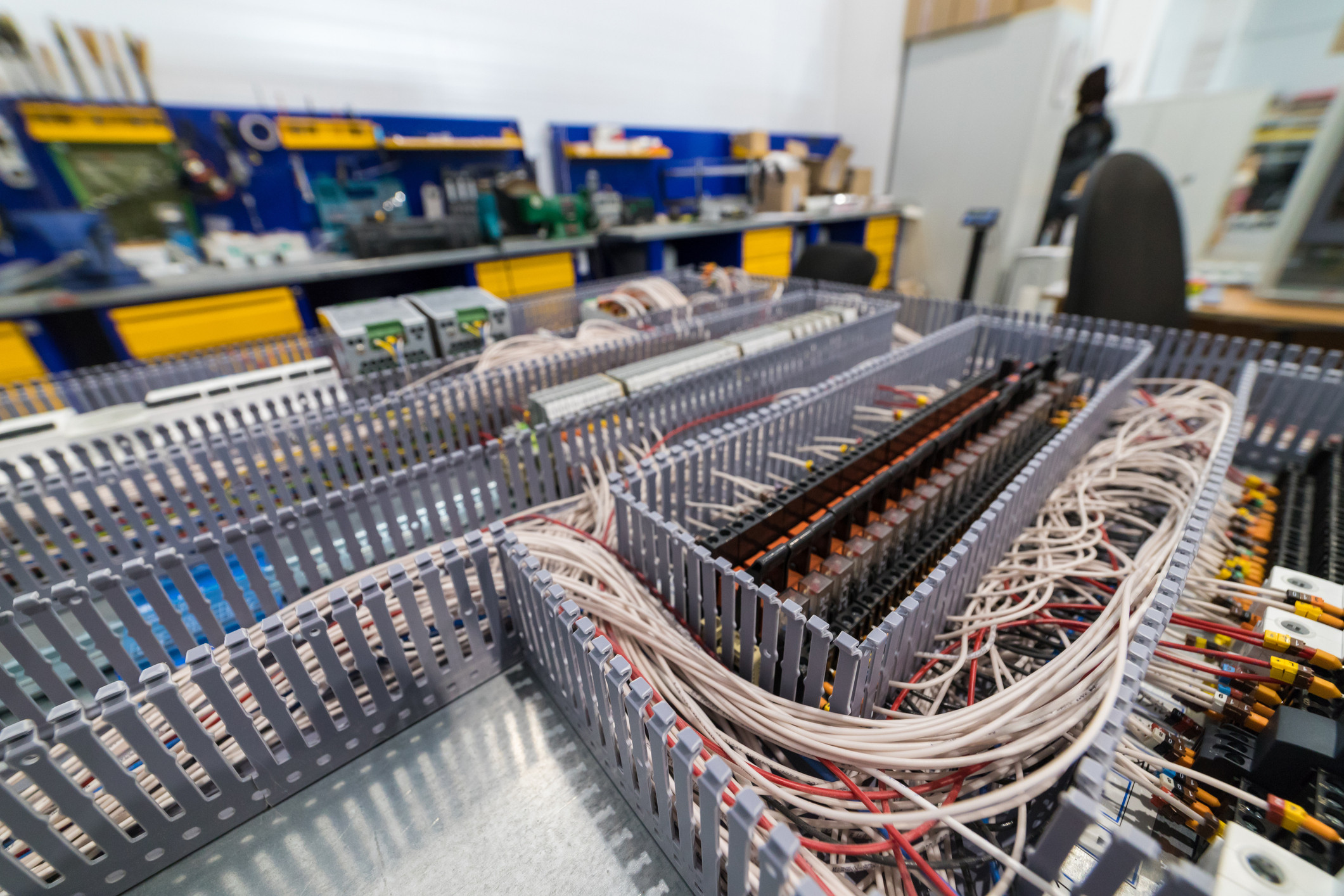

“Two contactors and a safety relay, so that makes category 3.” Everything looks right in the control cabinet. The purchasing list agrees. Then a contactor welds, and the design has to prove how much of that neat logic survives in the real machine.
The operator opens a conveyor guard. The control system de-energises coil K1, but its contacts have welded. The motor remains powered. The command was correct. The contactor simply did not execute it. A second contactor may still disconnect the drive. Diagnostics may expose the fault and prevent another start. It all depends on the architecture.
ISO 13849-1 safety categories describe a subsystem’s resistance to faults and its behaviour after they occur. The difference between B, 1, 2, 3 and 4 is easiest to understand through one repeated task: disconnecting power from a drive, including when something in the circuit has failed. During acceptance testing, every healthy system can look impressive. Categories start earning their keep when the system is no longer healthy.
Define the task before choosing devices for the cabinet
An operator must adjust a workpiece. The belt has to stop before access to the hazardous area and remain stopped while the guard is open. The designer derives these requirements from the risk assessment to ISO 12100, then records them in the safety requirements specification — SRS.
The complete safety function includes detection of the open guard, the control decision and disconnection of the drive. Each part may be treated as a subsystem. In the examples below, the output subsystem changes: its contactors, wiring and monitoring. Its task, or subfunction, is to remove power from the drive.
A contactor is an electrically controlled switching device. Voltage at A1–A2 closes the power contacts carrying current to the motor. When the coil is de-energised, a healthy contactor opens them. Welded contacts remove precisely that capability.
With two contactors, K1 and K2, motor current passes through both in series. Opening either interrupts the circuit. Each contactor, together with its control path, provides a separate disconnection path: a channel.
Category B: K1 welds, so power remains connected
One contactor, K1, disconnects the drive. When the guard opens, the control system de-energises the coil, the contacts open and the motor loses power. That may work perfectly for thousands of cycles.
During the next start, the contacts weld. The conveyor continues running, so the operator notices nothing yet. Then the guard opens. Coil voltage disappears, but current still flows to the motor. There is no second component capable of interrupting it. One fault has removed the subsystem’s ability to disconnect the drive.
If the coil wire had broken instead, a healthy contactor would have dropped out. Different fault, different consequence. “The contactor will drop out on failure” sounds convincing only when the speaker gets to choose the failure.
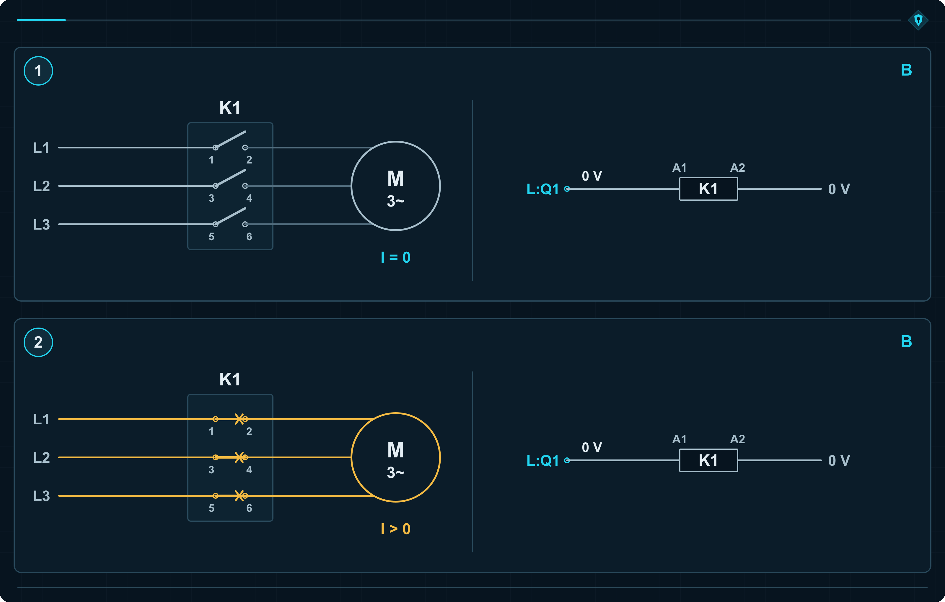
Category B requires basic safety principles and components selected for the actual operating conditions. The contactor must withstand the load, switching duty and cabinet temperature. The letter B is not permission to install whatever happened to be left in stores.
When does category B give PL a, and when PL b?
Two circuits can look identical while having very different dangerous failure rates. One contactor starts a motor once per shift. Another switches for every workpiece. The model may be identical; the number of operations is not.
The designer considers the component’s endurance and the machine’s real duty. This produces MTTFD, the mean time to dangerous failure. The higher the value, the less frequently dangerous failures are statistically expected. Every channel component whose failure could prevent disconnection must be included.
Category B subsystem examples from Table K.1
| Channel MTTFD | PFH — average frequency of a dangerous failure per hour | Achieved PL |
|---|---|---|
| 10 years | 1.14 × 10⁻⁵ 1/h | PL a |
| 12 years | 9.51 × 10⁻⁶ 1/h | PL b |
| 20 years | 5.71 × 10⁻⁶ 1/h | PL b |
At 10 years the result is PL a. At 12 years it is already PL b because PFH falls below 10⁻⁵ 1/h. Reliability has changed. Behaviour after K1 welds has not.
MTTFD is statistical. “20 years” is neither a twenty-year warranty nor an automatic replacement date. Replacement intervals must account for the component’s operating conditions and usage limits.
These values apply only to the output subsystem. The complete function also includes the sensor and logic: PFH of input + PFH of logic + PFH of output. The sum is compared with the PL bands, while the lowest PL of any subsystem provides an additional limit. An output at PL b can therefore contribute to a complete function that achieves only PL a.
Category B can achieve no more than PL b. If PLr is d, another solution is required. Repeating a successful guard-opening test during acceptance will not move that limit. Everything depends on one channel, and welded K1 removes the protection.
Category 1: the same failure should occur less often
The drive is still disconnected by one K1. The designer now raises the requirements for its reliability and application. In addition to category B principles, category 1 uses well-tried components and well-tried safety principles. In the simplified method, channel MTTFD must be high: from 30 to 100 years.
“Well-tried” applies under defined operating conditions. A contactor that switched heaters reliably for years may now face a motor with high starting current and frequent starts. The familiar logo remains. The load has changed.
Selection must be supported by documented experience from similar applications or by properties demonstrated through design, verification and validation under the relevant standards. ISO 13849-2 also identifies components and conditions under which they may be considered well-tried. The designer applies principles that reduce the occurrence of faults or their dangerous consequences.
Then K1 welds anyway. The coil is de-energised, the contacts remain closed and the motor remains powered. Category 1 reduces the probability of the event. It does not create a second channel.
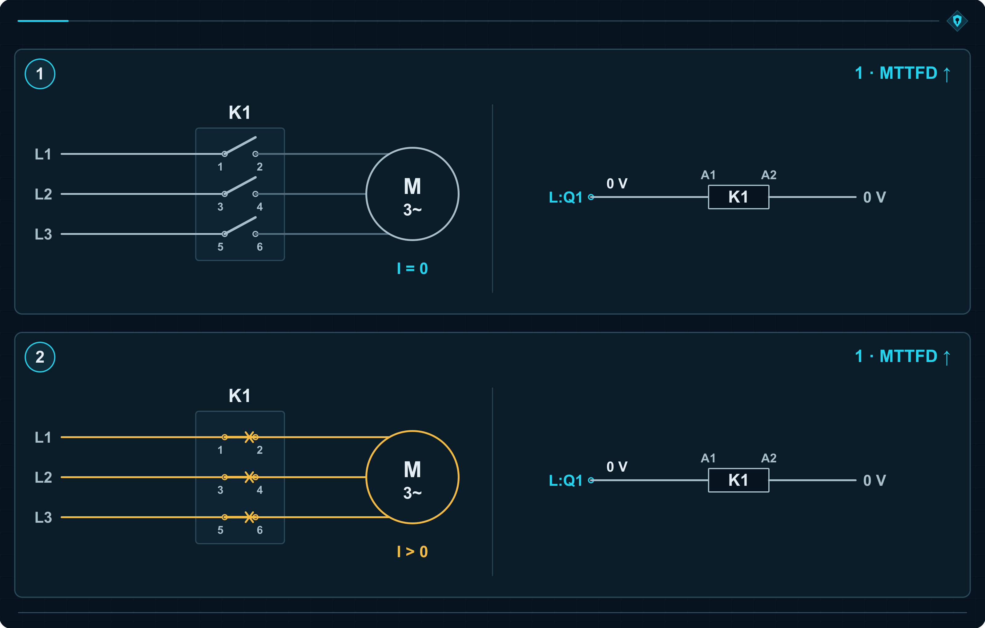
Higher reliability: from PL b to PL c
For a channel MTTFD of 30 years, Table K.1 gives PL b. At 39 years, PFH drops below 3 × 10⁻⁶ 1/h and the result becomes PL c.
Category 1: example MTTFD, PFH and PL values from Table K.1
| Channel MTTFD | PFH — average frequency of a dangerous failure per hour | Achieved PL |
|---|---|---|
| 30 years | 3.80 × 10⁻⁶ 1/h | PL b |
| 39 years | 2.93 × 10⁻⁶ 1/h | PL c |
| 100 years | 1.14 × 10⁻⁶ 1/h | PL c |
Category 1 tops out at PL c. A better contactor matters because it fails less often. If it fails through welded contacts, there is still no second route to disconnect the drive. Greater reliability does not turn a single channel into redundancy.
Category 2: the system checks whether K1 obeyed the command
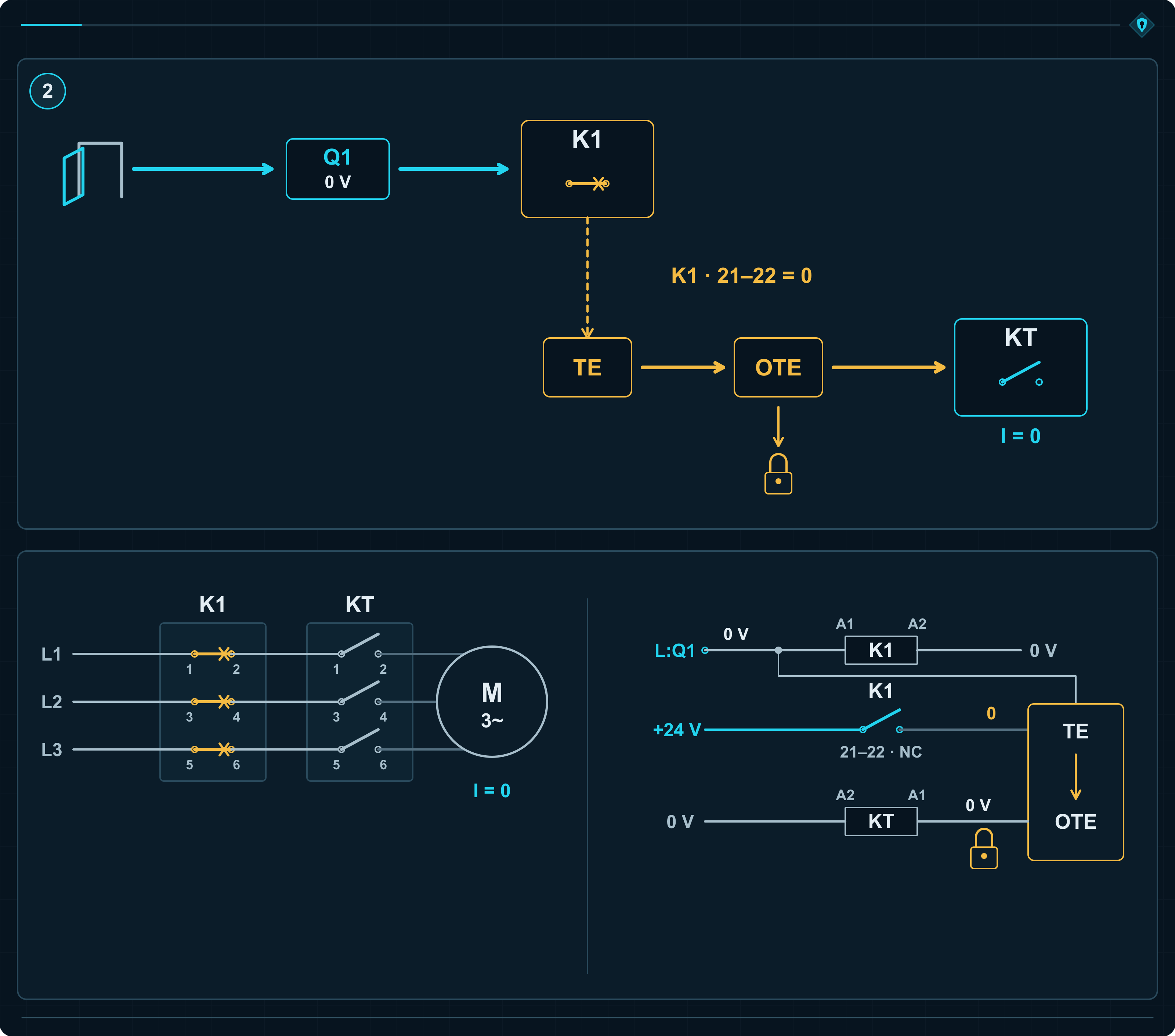
The operator opens the guard. The control system de-energises K1 and waits for confirmation that its power contacts have opened. This time, execution of the command is tested.
A mirror contact provides the feedback. Its mechanical design prevents it from closing while a power contact remains welded. The system therefore receives one of two messages: K1 opened the circuit, or K1 failed to obey.
K1 welds. Confirmation does not return. The test detects the fault and initiates a response. In this example, an additional contactor KT, connected in series with K1, disconnects power. The control system prevents another start until the fault has been removed.
ISO 13849-1 calls the test equipment TE and its output OTE. Here, OTE controls KT. K1 belongs to the functional channel that performs normal disconnection. TE and OTE form the test channel, which checks execution and initiates the fault response.
There are two contactors in the cabinet, yet this remains a category 2 example. KT is commanded to disconnect after the problem with K1 has been detected. Counting devices has already lost its argument with reading the circuit diagram.
Healthy yesterday, welded during today’s start
K1 passes a test correctly. During its next operation, the contacts weld. Until the next test, the functional channel is defective. The previous result concealed nothing; the machine simply failed afterwards.
That is why category 2 may lose the subfunction between tests. The designer must define when testing occurs and how quickly the system reacts. If the test begins when the guard opens, fault detection, KT disconnection and stopping must all happen before a person can reach the hazard.
For PLr d, OTE must initiate a safe state and maintain it until the fault is removed. KT provides that response here. A red message on the display would leave the motor energised. It would merely explain, with admirable clarity, why the protection was not working.
Test frequency and reaction time. Clause 6.1.3.2.4 requires either a test frequency at least 100 times the demand rate of the safety function, or an immediate test on demand that detects the fault and brings the machine to a safe state before the hazard can be reached. Opening the guard is the demand on the safety function. A 100:1 ratio does not mean 100 tests before every guard opening.
The MTTFD of the TE–OTE test channel must exceed half the MTTFD of the functional channel. Every part of the functional channel requires at least low diagnostic coverage. Category B requirements, well-tried safety principles and measures against common cause failure between the channels also apply.
For PLr up to and including c, OTE should also initiate a safe state where reasonably practicable. Where that cannot be achieved, a warning may be sufficient under the standard. At PLr d, a safety-related response is required.
Testing can deliver PL d, but reliability still matters
DC, diagnostic coverage, describes the effectiveness of detecting dangerous failures. For the complete subsystem, average diagnostic coverage DCavg accounts for the dangerous failure rates of its constituent parts.
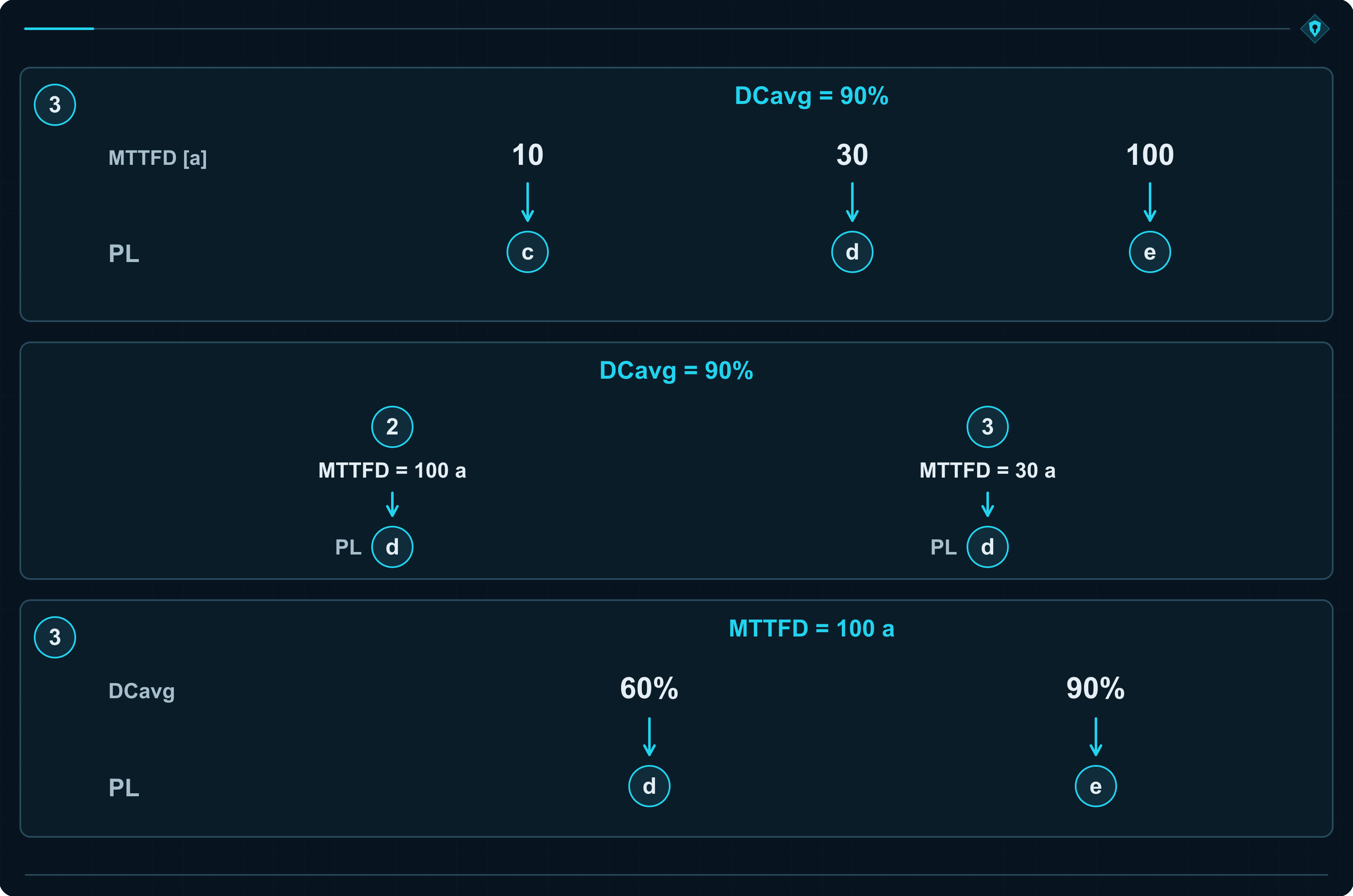
With the same DCavg = 90%, category 2 gives PL a at a functional-channel MTTFD of 3 years, PL b at 10 years, PL c at 30 years and PL d at 100 years. Testing exists in every case. What changes is the number of failures the architecture must handle.
Category 2 subsystem with DCavg = 90%: examples from Table K.1
| Functional-channel MTTFD | PFH — average frequency of a dangerous failure per hour | Achieved PL |
|---|---|---|
| 3 years | 1.99 × 10⁻⁵ 1/h | PL a |
| 10 years | 5.14 × 10⁻⁶ 1/h | PL b |
| 30 years | 1.21 × 10⁻⁶ 1/h | PL c |
| 100 years | 2.29 × 10⁻⁷ 1/h | PL d |
In category 2, protection depends on the test detecting the fault and the system reacting in time. The test schedule and reaction time are not commissioning details. They are part of the safety design.
Category 3: K2 disconnects without waiting for a test result
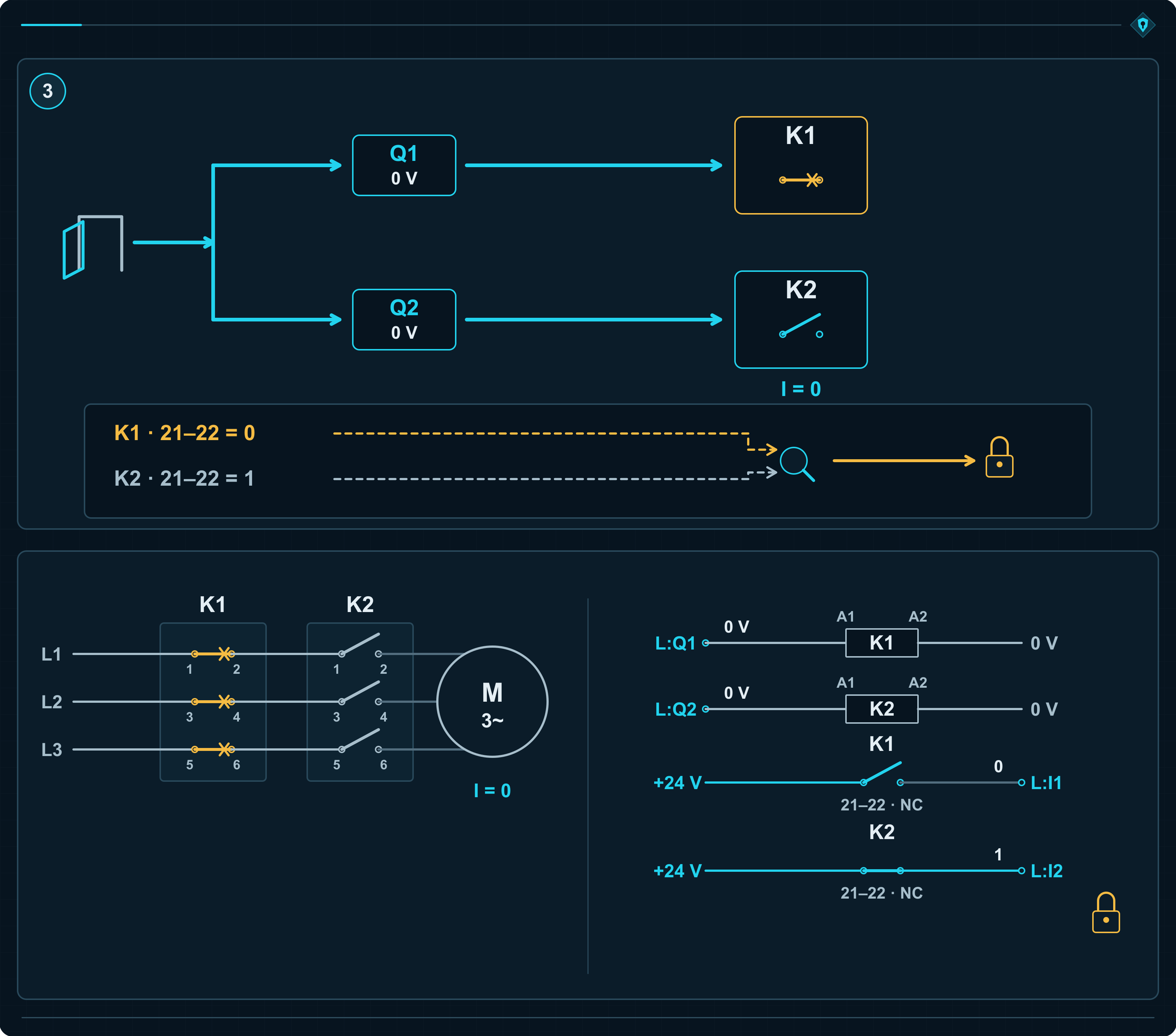
K1 and K2 are connected in series in the motor supply. When the guard opens, the control system commands both to switch off. Each contactor has its own control path, and either can interrupt drive power independently.
K1 remains welded. K2 opens and interrupts current. The second channel performs the protective task despite the fault in the first.
This is the decisive difference from category 2. There, KT intervened after a test detected the fault in K1. Here, K2 receives a switch-off command because the guard opened. It does not wait for K1 diagnostics.
The conveyor stopped, but the repair is still required
The operator sees the usual result: the belt stops. Inside the cabinet, one contactor is already defective. Diagnostics detect that K1 failed to confirm opening and prevent another start.
K2 completed the task for the failed channel. It did not repair K1. If the control system allowed continued operation with the known fault, the next disconnection would depend entirely on K2.
Category 3 requires the subfunction to remain available after a single fault. This applies to components and connections throughout the assessed subsystem. If one control fault can keep both coils energised, both contactors may execute the wrong command flawlessly.
Category 3 also requires at least low diagnostic coverage. A single fault must be detected at the demand on the safety function or before the next demand where reasonably practicable. Some faults may remain undetected. Their later accumulation can defeat the protection. That is where the distinction from category 4 begins.
Category 3 can achieve PL c, d or e
With DCavg = 90% and an MTTFD of 10 years for each channel, Table K.1 gives PL c. At 30 years it gives PL d; at 100 years, PL e. “Category 3 means PL d” is a convenient shortcut that loses two valid outcomes.
Category 3 subsystem with DCavg = 90%: examples from Table K.1
| MTTFD of each channel | PFH — average frequency of a dangerous failure per hour | Achieved PL |
|---|---|---|
| 10 years | 1.36 × 10⁻⁶ 1/h | PL c |
| 30 years | 2.65 × 10⁻⁷ 1/h | PL d |
| 100 years | 4.29 × 10⁻⁸ 1/h | PL e |
MTTFD applies to each channel separately. Two channels rated at 30 years do not become one channel rated at 60 years. Category B requirements, well-tried safety principles and measures against common cause failure still apply.
K2 disconnects the drive despite the K1 fault. Diagnostics then decide whether another cycle may be authorised. Redundancy preserves the subfunction; monitoring prevents the machine from quietly continuing with half its protection gone.
Category 4: faults missed by diagnostics also become the problem
After K1 welds, K2 disconnects the drive and the control system prevents restart. The same happened in the category 3 example. The difference appears only when the analysis goes further: what does the system detect, when does it detect it, and what happens to faults that escape detection?
In category 4, a single fault must leave the safety function effective and be detected at the demand or before the next demand. If detection within that time is impossible, an accumulation of faults must still leave the protection effective.
The system also checks whether the feedback is telling the truth
Each contactor has a separately monitored mirror contact. The control system checks its response throughout the operating cycle:
- Before starting, both contactors are off. Their mirror contacts must confirm that the power paths are open.
- After a contactor is energised, its “open” confirmation must disappear within the defined time.
- After switch-off, the confirmation must return.
With welded K1, the final confirmation does not return. K2 disconnects the drive and the logic prevents restart. Coil voltage changes from 0 → 24 → 0 V, while expected open confirmation changes from 1 → 0 → 1.
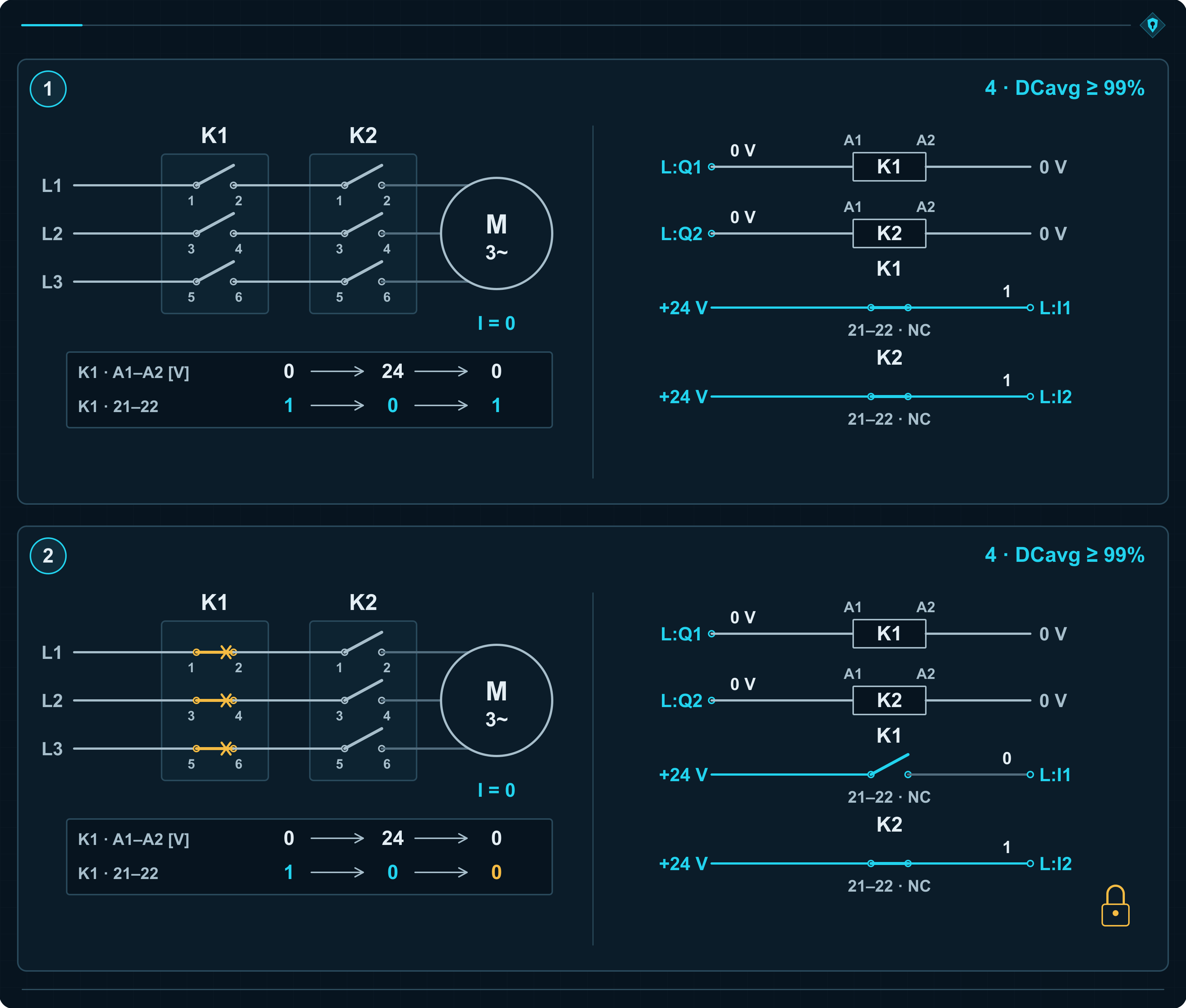
Why check that the confirmation disappears as well as returns? The two mirror-contact wires could short together. The signal would then say “K1 open” continuously, including while the contactor was energised. A system checking only for that signal before start would accept false confirmation.
Dynamic monitoring detects the contradiction: K1 received an energise command, but the “open” feedback remained present. The control system switches off its outputs and prevents operation. The operator may press reset, but reset will not separate shorted wires or welded contacts.
The same diagnostic technique may also be used in category 3. Category 4 is determined by the behaviour of the complete subsystem under the considered faults and their accumulation, not by one clever feedback check. Control circuits, feedback paths and the effects of their failures must all be analysed.
Two valves show why this matters
V1 and V2 are seat valves connected in series in the oil supply to a cylinder. Either can stop the supply independently. Sensors monitor the position of their closing elements.
The seat seal in V1 fails. The closing element reaches the “closed” position, but oil leaks through the damaged seal. The position sensor is still telling the truth. Healthy V2 stops the flow, so nothing visible happens at the machine.
Later, for an independent reason, V2 also begins to leak. Flow through both valves is now sufficient to cause dangerous cylinder movement. The display still shows two “closed” confirmations. They agree perfectly and are completely useless for detecting this failure.
This is an accumulation of undetected faults that may defeat category 3 protection. For category 4, that chain must be broken: detect the relevant leakage in time or ensure that the safety function remains effective under the considered fault accumulation.
A separate leakage test for each valve checks what the position sensors cannot. Leakage might raise pressure in an isolated test volume downstream of the valve but separated from the cylinder. A pressure sensor detects the rise and the system prevents further operation. If both closed valves were tested together, tight V2 could hide leaking V1.
The pressure threshold and test time must reveal safety-relevant leakage before a hazard develops. The design must also address residual pressure downstream. Stopping fresh oil does not remove energy already stored in the system.
The 99% must come from real diagnostic action
Category 4 requires high DCavg, at least 99%, and high MTTFD for each channel. The 99% concerns the dangerous failure rate actually detected. Detecting nine rare failure modes while missing one common mode may still produce poor coverage. The checklist looks healthier than the machine.
Category 4 subsystem with DCavg = 99%: numerical examples from Table K.1
| MTTFD of each channel | PFH — average frequency of a dangerous failure per hour | Achieved PL |
|---|---|---|
| 30 years | 9.54 × 10⁻⁸ 1/h | PL e |
| 100 years | 2.47 × 10⁻⁸ 1/h | PL e |
| 2,500 years | 9.06 × 10⁻¹⁰ 1/h | PL e |
The category 4 model permits channel MTTFD up to 2,500 years. Again, that is a statistical parameter, not a service promise. Category B principles, well-tried safety principles and CCF measures remain mandatory.
Clause 6.1.3.2.6 notes that considering combinations of two faults may be sufficient in practice. Excluding undetected faults with very low probability requires documented and verified analysis, such as FMEA. Diagnostics must test the ability to perform the safety task. A valve can confirm the correct position and still leak oil.
High diagnostic coverage is not a number selected in calculation software. It must be justified by failure modes that are actually detected, at the required time, followed by an effective response.
Five categories, one welded K1
In categories B and 1, welded K1 leaves the motor powered. In the category 2 example, KT disconnects after TE detects the fault. In categories 3 and 4, K2 disconnects because it receives the switch-off command when the guard opens. Diagnostics expose the failure and prevent another cycle.
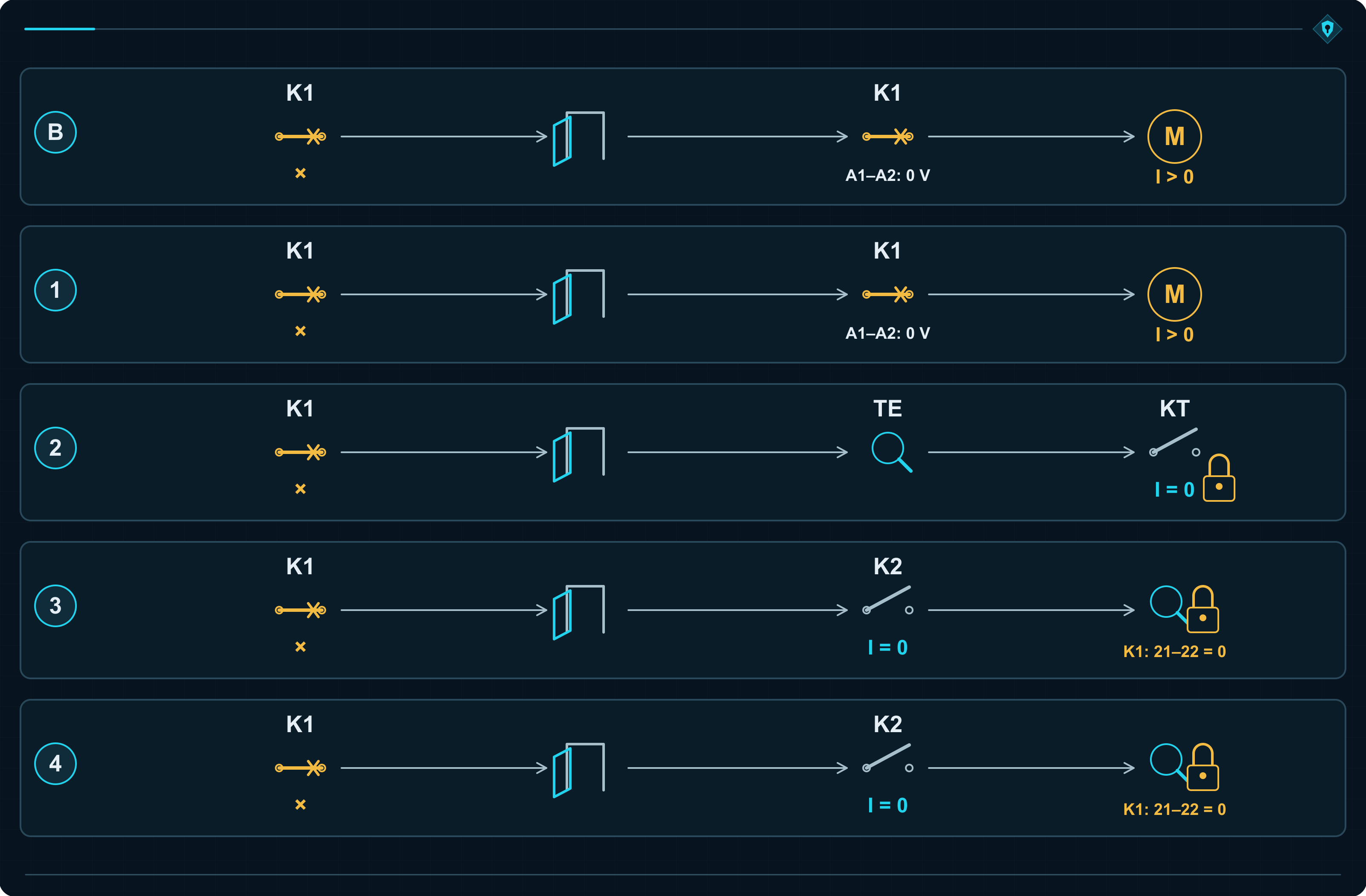
That is why assessment cannot stop after the first successful protective reaction. The designer must ask what remains broken, whether it was detected and what the next demand will encounter.
Two contactors can lose to the same short circuit
So far, K1 failed and K2 saved the disconnection. Now a short circuit occurs downstream of K2. Short-circuit current flows through both closed contactors and damages both. The second channel has just met the same cause as the first.
This is CCF: common cause failure. In categories 3 and 4 it concerns both functional channels; in category 2, the functional and test channels. The designer must reduce common exposure through concrete engineering measures.
K2 closes first and opens last
K2 closes first while K1 remains open, so motor current does not yet flow. K1 then closes and switches the load. During stopping, the sequence is reversed: K1 interrupts current and K2 opens shortly afterwards, without load current.
Both carry the same current during operation, but their switching duties differ. K2 normally avoids making starting current and breaking the load, reducing electrical contact wear. Its mechanism still moves every cycle, so mechanical wear remains.
K2 must nevertheless be selected to interrupt the full load independently. That is exactly what it must do after K1 welds. Its switch-off must occur within a defined time and must not wait for K1 confirmation, because welded K1 will never provide it. Delays and device operating times must remain within the required safety-function response time.
Short-circuit protection must limit the effects of the shared event
Switching sequence creates different making and breaking duties. During a short circuit with both contactors closed, current stresses both. Protective device F must interrupt it; the resulting damage depends on the current magnitude and clearing time.
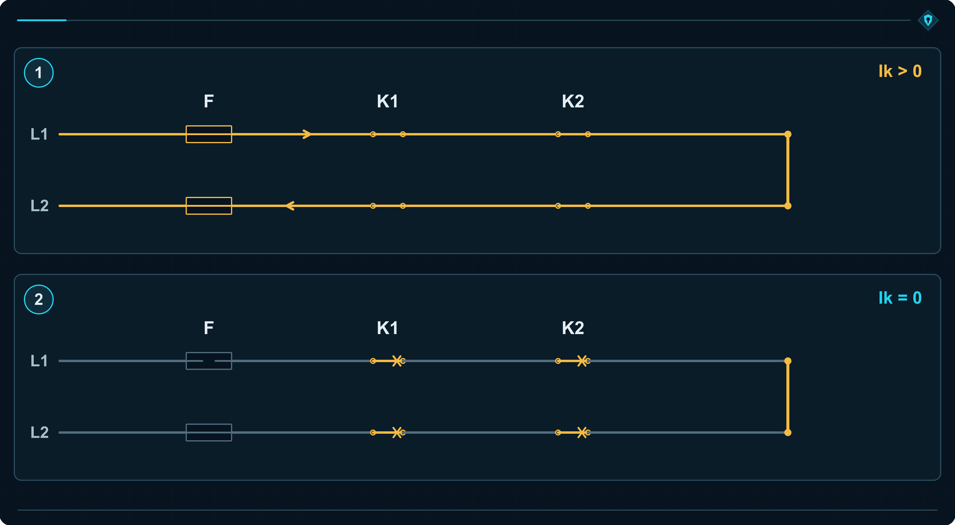
The designer determines the prospective short-circuit current at the installation point and checks the complete combination: the specific contactor, protective-device type and rating, voltage and application conditions. Manufacturer data establish whether those devices coordinate correctly. Motor rated current alone says too little.
Contacts welded during the short circuit can remain closed after F operates. The fuse interrupts current. Contactor repair is not included. Before restarting, both devices must be inspected and damage corrected.
Type 2 coordination and welded contacts. IEC 60947-4-1, clause 8.2.5.1, permits contact welding even with type 2 coordination. The manufacturer specifies the required maintenance action. Substituting a different protective device can invalidate the coordination.
Shared route, shared power supply, shared overheating
Both coil cables run in one bundle. Crushing the bundle shorts both control paths to +24 V. Separate protected routes and segregated terminals reduce the chance of one fault affecting both channels.
A shared power supply fails and produces excessive voltage. The designer checks its fault behaviour and provides suitable voltage limitation or external protection for the supplied circuits.
Both contactors sit above a variable-speed drive. After a fan failure, the temperature exceeds their rating. Device layout, spacing and cooling must account for that condition. An open cabinet during acceptance testing usually enjoys excellent ventilation.
Both channels run beside motor cables from the drive. Separation, shielding and equipotential bonding help reduce common electromagnetic interference. Immunity must match the real operating environment.
Annex F structures the assessment as a points system. At least 65 points are required for the measures applied. Examples include 15 points for separation, 15 for protection against relevant overcurrents and overvoltage, 25 for electromagnetic interference measures and 10 for other environmental factors.
The threshold can be justified with identical contactors. Diversity of design, technology, loading or manufacturer provides up to 20 points in one item. Two brands printed on the same underlying product are still the same product. Each measure must be fully implemented throughout the assessed subsystem; partial implementation scores zero.
A second channel helps only while a common cause does not remove the ability of both channels to act. Redundancy without CCF control is two devices sharing the same trap.
Where are the two channels inside a sensor, relay or PLC?
K1 and K2 are easy to point at. In electronics, channels may exist inside one enclosure. ISO 13849-1 defines the logical architecture; the manufacturer describes how a particular device implements it internally.
Two sensors on one guard
Inductive sensors S1 and S2 detect a metal target on a closed guard. Each provides its own signal to a separate control input. Operation requires both “closed” confirmations.
S1 fails and permanently reports “closed”. The operator opens the guard and the target moves away from both sensors. Healthy S2 changes state, and the control system commands a stop. Loss of one confirmation is sufficient to trigger the response.
One safety sensor with two OSSD outputs
An inductive safety sensor may include diagnostics and two monitored electronic safety outputs, OSSD1 and OSSD2. OSSD stands for output signal switching device. When the target moves away, both outputs switch off and request a stop. Diagnostics also supervise their ability to switch off.
An ordinary sensor with two outputs may behave differently. One electronic circuit detects the target, and the same result controls both outputs. The NO (normally open) output switches on when metal is detected, while the NC (normally closed) output switches off. If the electronics falsely detect metal while the guard is open, both outputs behave exactly as they would with the guard closed. Comparing their opposite states will not reveal the error. The control system has received two versions of the same mistake.
Splitting one signal across two inputs produces a similar illusion. Two wires are not automatically two independent channels.
Safety relay and controller
A conventional safety relay may contain two internal relays, R1 and R2. Their enabling contacts are connected in series. If an R1 contact welds, R2 can still open the output. Mechanically linked monitoring contacts reveal the weld and prevent restart.
A safety-related programmable logic controller (PLC) may use two processors and compare their results. If a fault makes one processor permit motion while the other requests a stop, the discrepancy initiates a protective response. Testing may also cover memory, programme execution, inputs and outputs.
Two copies of a programme in an ordinary PLC may still run on one processor. A processor failure affects both copies. Copying code is easier than engineering fault resistance, and it delivers a different result.
Safety light curtain
The operator interrupts beams between the transmitter and receiver. The light curtain switches off OSSD1 and OSSD2. If failed OSSD1 remains on, OSSD2 switching off is still enough for the connected control system to command a stop. Each output goes to its intended input, and diagnostics cover the outputs and their connections.
From the device documentation, the designer verifies achieved PL, category, response time and required connection method. Only then can the properties of the completed subsystem be used correctly in the specific safety function.
The same PL can hide different fault behaviour
One designer obtains PL d using category 2; another obtains PL d using category 3. Both calculations may be correct. The first uses a more reliable tested channel. The second uses two functional channels.
Two architectures achieving the same PL
| Category | Channel MTTFD | DCavg | PFH [1/h] | PL |
|---|---|---|---|---|
| 2 | 100 years | 90% | 2.29 × 10⁻⁷ | d |
| 3 | 30 years | 90% | 2.65 × 10⁻⁷ | d |
For category 2, MTTFD applies to the functional channel. For category 3, it applies to each of the two channels. Both PFH values fall within PL d, but category 2 can lose the subfunction between tests, while category 3 retains it after a single fault.
If the SRS or a type-C standard for the machine requires the safety function to remain available after one fault, the designer must provide that behaviour. The letter d alone does not settle the architecture.
The same category with better diagnostics
For category 3 with MTTFD = 100 years for each channel, raising DCavg from 60% to 90% moves the result from PL d to PL e.
Category 3 with MTTFD of each channel = 100 years
| DCavg | PFH [1/h] | PL |
|---|---|---|
| 60% | 1.01 × 10⁻⁷ | d |
| 90% | 4.29 × 10⁻⁸ | e |
Higher diagnostic coverage must come from more effective fault detection and an appropriate response. Monitoring changes in a feedback signal can expose a short circuit that permanently reports an open contactor. That changes system behaviour. Changing a field from 60 to 90% in calculation software changes only the printout.
Assumptions behind the Table K.1 examples. The values come from the subsystem models in ISO 13849-1:2023. The method in clause 6.1.8 assumes a 20-year mission time, constant failure rates and appropriate CCF measures. Components that wear out sooner must be handled according to their usage limits.
Category 2 also requires compliance with test-channel reliability and either the test-frequency ratio or the reaction-time condition at demand. For periodic testing, the displayed PFH values correspond to a test-to-demand ratio of at least 100:1. Note 1 to Table K.1 estimates a ratio of at least 25:1 by multiplying the tabulated PFH by 1.1. Values for low, medium and high DCavg are calculated at 60%, 90% and 99% respectively.
PL expresses the performance level. The category explains how the architecture behaves under faults. A defensible design needs both. One number cannot replace the other.
The contactors are ready to disconnect, but the command never arrives
The K1–K2 subsystem achieves PL e. The guard sensor, however, falsely informs the logic that the door is closed. Motion remains enabled, so both contactors stay energised. They may be healthy and perfectly monitored. The problem occurred earlier in the function.
The designer must therefore assess the complete chain: input → logic → output, including connections. For a series combination of subsystems with known PFH values, those values are added. The overall PL is limited by both the sum and the lowest PL of any subsystem.
Three subsystems at 4 × 10⁻⁸ 1/h each produce 1.2 × 10⁻⁷ 1/h in total: PL d. Each subsystem individually fell within PL e. The arithmetic is simple. The complete function has more places where a dangerous failure can occur. The calculation is explained further in the article on calculating PL to ISO 13849-1.
After power is removed, the belt still needs time to stop. Protection must act before a person reaches the hazard. The practical consequence is clear when calculating the safety-light-curtain distance after a response-time change.
When subsystems assessed through different methods are combined, it is also useful to understand the relationship between ISO 13849-1 and IEC 62061.
After a few years, somebody will replace K1
The new contactor has the same rated current and fits the rail. The technician also needs the correct mirror contact, suitable operating times and endurance data. Those properties formed part of the original design. “24 V, same amperes” misses exactly what the diagnostics need.
Documentation must show why the device was selected, what the system monitors and how it reacts to a fault. Otherwise, the only remaining control measure is a telephone call to the programmer and the hope that one person remembers the reason for every condition.
Extract from record OUT-01 — assumptions for the K1–K2 example
| Field | Record |
|---|---|
| Scope | K1–K2 output subsystem, including connections and monitoring; task: disconnect power from the drive. |
| Considered fault | K1 remains closed despite the switch-off command. |
| Required response | K2 independently disconnects the drive. Failure of K1 feedback to return exposes the fault and prevents restart. |
| Evidence required | Fault analysis and test T-01: verify disconnection by K2, response time, fault detection and restart prevention. Record the result for the specific system version. |
The complete record links the decision to the SRS, circuit-diagram revision, MTTFD, DCavg and CCF evidence, and validation results. It also justifies any fault exclusions.
Download the category justification record (PDF, EN): a worked K1–K2 example and a fillable form for your own design in one file.
A manager does not need to calculate PFH personally. Ask the supplier to trace one fault on the circuit diagram: what fails, what still protects the person, when the control system notices and where the result was validated. That leads to a much better discussion than asking which brand of safety relay was fitted.
Two contactors are purchasing-list entries. Their architecture, diagnostics, fault response and documented justification are what support a safety category.
Sources
The conveyor, contactor and valve examples illustrate the requirements. PFH values and corresponding PL results are taken from Table K.1 of ISO 13849-1.
- ISO 13849-1:2023, clauses 4.5, 5.1, 5.2.1 and 5.3–5.5: information from risk assessment, SRS, PLr and subsystem decomposition; definitions 3.1.45–3.1.47 and clauses 6.1.3.1–6.1.3.2.1: subsystem, channel and architectures.
- ISO 13849-1:2023, clauses 6.1.3.2.2–6.1.3.2.6: requirements for categories B–4, fault response, testing and fault accumulation; definitions 3.1.49–3.1.50 and clause 6.1.11: well-tried safety principles and well-tried components.
- ISO 13849-1:2023, Tables 2, 6 and 7, clauses 6.1.4–6.1.5 and 6.1.8, Annexes C–E and Table K.1 with Notes 1–2: PL, PFH, MTTFD, DC, endurance data, switching operations and numerical-model assumptions.
- ISO 13849-1:2023, clause 6.1.6, Annex F and Table F.1: CCF, measures against common exposure, points assessment and the 65-point threshold; F.3.2: diversity; F.3.3 and F.3.6: protection, interference and environmental conditions.
- IEC 60947-4-1, clause 8.2.5.1: coordination between contactors and short-circuit protective devices, including type 2 coordination; clauses 8.2.4.3.1–8.2.4.3.2 and Annex B: mechanical and electrical endurance; Annex F: mirror-contact properties and identification.
- ISO 13849-1:2023, clause 6.1.10, definitions 3.1.29–3.1.30 and 3.1.51–3.1.52, Annex E and Table E.1: fault analysis, monitoring, testing and plausibility checking; clause 7 and Annex N: software and pre-assessed platforms; clause 13.2: integration information.
- ISO 4413, clause 5.4.4.1: valve leakage and suitability for safety-related applications; clauses 5.4.7.1–5.4.7.2.1: unintended movement, energy isolation and pressure dissipation.
- ISO 13849-1:2023, clause 6.2.2 and clause 8: subsystem combination, PFH summation and limits on achieved PL; clause 5.2.2.2: stopping; clauses 10.1.1–10.1.2, 10.8 and 12: validation, records and technical documentation.